Variable toe angle control system for a vehicle

a control system and variable toe angle technology, applied in adaptive control, computer control, instruments, etc., can solve the problems of difficulty in providing a fail-safe mechanism and the size of the actuator and hydraulic pressure generator, and achieve the effect of increasing the size of the system

Inactive Publication Date: 2011-01-18
HONDA MOTOR CO LTD
View PDF19 Cites 14 Cited by
  • Summary
  • Abstract
  • Description
  • Claims
  • Application Information

AI Technical Summary

Benefits of technology

[0006]In view of such problems of the prior art, an object of the present invention is to provide a variable toe angle control system for a vehicle that can be incorporated with a fail-safe mechanism without complicating the structure, increasing the size of the system or requiring any additional power requirements.
[0007]Another object of the present invention is to provide a method for controlling the toe angle of a vehicle that allows a fail-safe mechanism to be incorporated in the hardware structure without complicating the structure, increasing the size of the system or requiring any additional power requirements.
[0010]Thereby, in any situation, the toe angles of the two wheels are made to agree with each other, although the toe angle control is disabled, the vehicle can continue to travel without incurring any major inconveniences. Therefore, according to the present invention, even when the variable toe angle control system becomes unable to provide a normal control function, there is no need for a return spring device that would be otherwise required to force the wheels to neutral positions and to ensure the capability of the vehicle to travel along a straight path so that the structure can be made simple and the power source may consist of a compact structure owing to the absence of the need to have the actuator produce a force to oppose the spring force of the return spring device for forcing the wheels to the neutral positions.

Problems solved by technology

However, according to this prior art, when extending the piston rod under a normal condition, the hydraulic pressure is required to be high enough to oppose the spring force which is capable of maintaining the toe angle against the reaction from the road surface in case of a failure of the actuator so that the actuator and hydraulic pressure generator are required to be relatively large in size.
When the actuator is based on the use of a threaded rod, and the lead angle of the thread is selected in such a manner that the actuator remains immobile owing to the friction, because the linear displacement of the actuator is impossible without turning the threaded rod, there is some difficulty in providing a fail-safe mechanism.

Method used


Image

  • Variable toe angle control system for a vehicle
  • Variable toe angle control system for a vehicle
  • Variable toe angle control system for a vehicle

Examples


Embodiment Construction

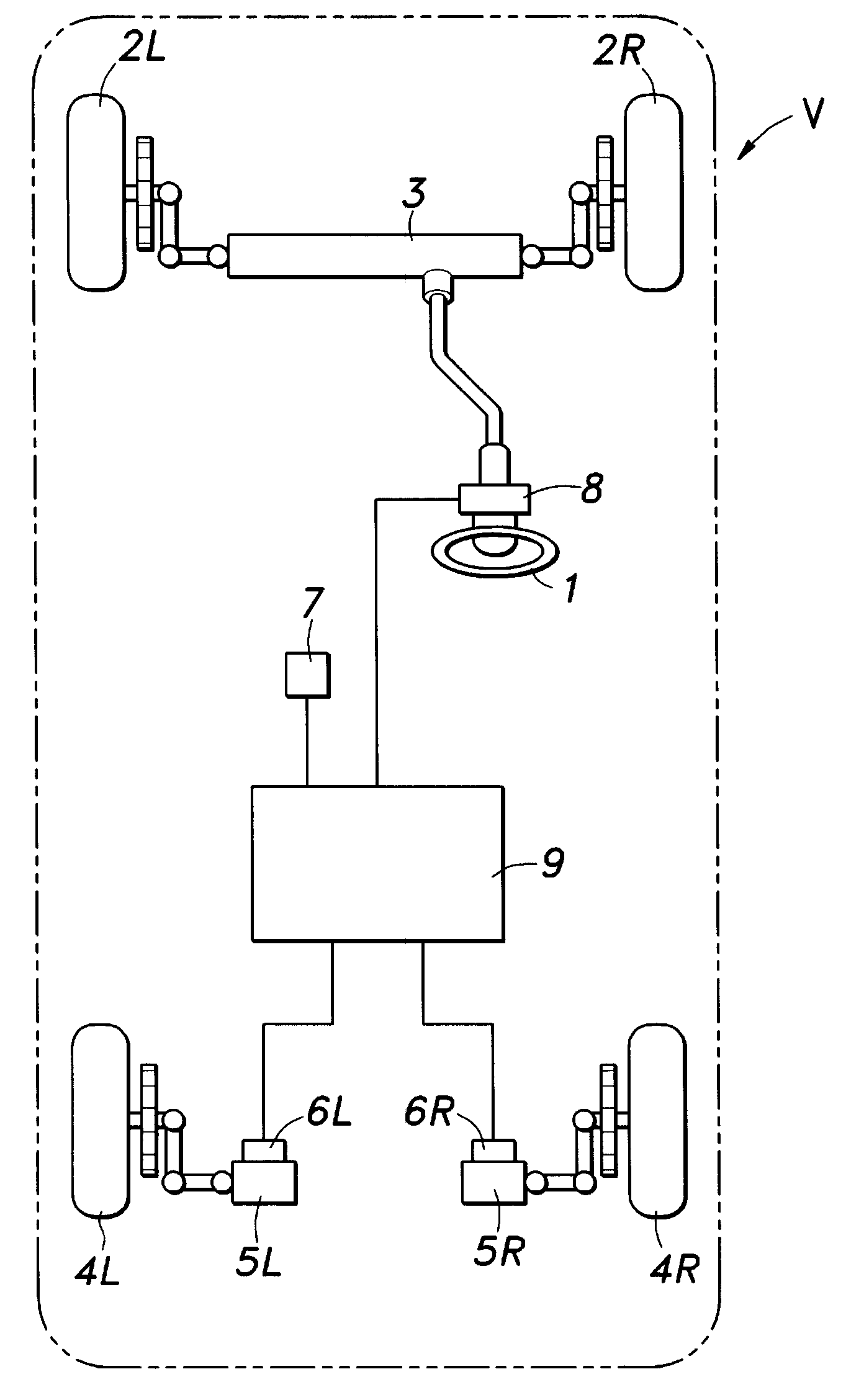
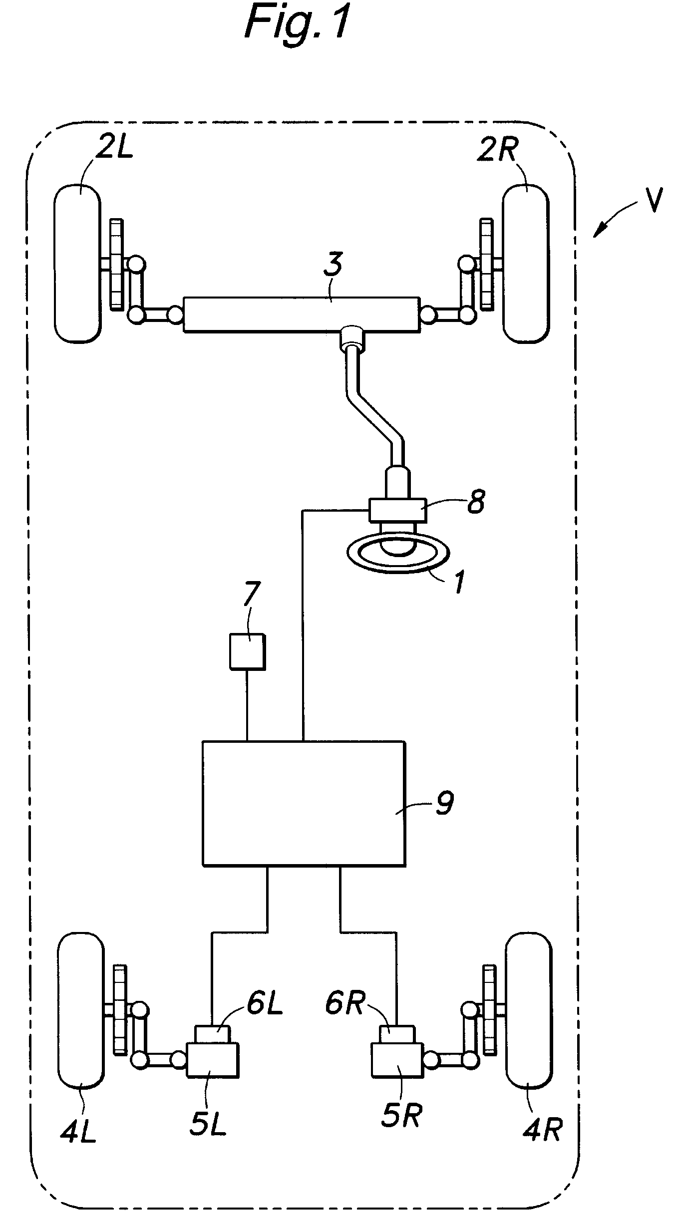
[0018]FIG. 1 shows an outline of a vehicle V to which the present invention is applied. The vehicle V comprises a front wheel steering device 3 for directly steering a right and left front wheel 2L and 2R according to a steering angle of a steering wheel 1. The vehicle V further comprises a right and left actuator 5L and 5R for individually changing the toe angles of a right and left rear wheel 4L and 4R by varying the lengths of parts, such as laterals links, of rear wheel suspension units supporting the right and left rear wheels 4L and 4R, respectively. The vehicle V further comprises a right and left toe angle sensor 6L and 6R for individually detecting the toe angles of the right and left rear wheels 4L and 4R, an accelerator sensor 7 for detecting a fore-and-aft acceleration acting upon the vehicle body to use it as a reference signal for determining a target control value in the variable toe angle control, and a steering angle sensor 8 for detecting the steering angle of the ...


PUM


Abstract

A variable toe angle control system for a vehicle that can be incorporated with a fail-safe mechanism. When a fault of the system is detected, at least one of toe-angle actuators is actuated to make toe angles of two wheels agree with each other. When one of the wheels has become fixed in position without regard to a control signal supplied to the corresponding actuator, the actuator for the other wheel is actuated so as to make the toe angles of the two wheels equal to each other. When at least one toe-angle sensor is found faulty, the actuators are both actuated until the actuators reach positions corresponding to stoppers. When information for determining target values of the toe angles of the right and left wheels is found faulty, the actuators are both actuated until the actuators reach positions corresponding to prescribed reference toe positions.

Description

TECHNICAL FIELD[0001]The present invention relates to a variable toe angle control system for a vehicle that can individually vary the toe angles of the right and left wheels.BACKGROUND OF THE INVENTION[0002]It is known to provide a linear actuator such as a hydraulic cylinder between a vehicle body end of a lateral link or a trailing arm of a wheel suspension unit for supporting each rear wheel and the vehicle body, and to individually control the toe angles of the right and left wheels by extending or retracting the corresponding linear actuators (see Japanese patent publication No. 8-25482 and Japanese patent laid open publication No. 9-30438).[0003]In such a system, a fail-safe mechanism is required so that the vehicle may be able to continue to travel without any inconvenience even in case of a failure of the system. For instance, the hydraulic actuator described in Japanese patent publication No. 8-25482 is provided with a piston rod that is resiliently urged by a spring membe...

Claims


Application Information

Patent Timeline
Patent Type & Authority Patents(United States)
IPC IPC(8): G05B13/00G06F7/00
CPCB62D7/148B62D17/00
Inventor HORIUCHI, YUTAKAKOIKE, AKIHKOSASAKI, HIROAKIYANAGI, TAKASHI
Owner HONDA MOTOR CO LTD
Why Eureka
Try Eureka