Recording in probe-based data storage devices

a data storage device and probe technology, applied in the field of probe-based data storage devices, can solve the problems of detection errors, loss of performance, indentations starting to interact in a non-linear way, etc., and achieve the effects of reducing the number of write signals, avoiding partial erasure, and increasing storage density

Inactive Publication Date: 2011-01-25
IBM CORP
View PDF3 Cites 2 Cited by
  • Summary
  • Abstract
  • Description
  • Claims
  • Application Information

AI Technical Summary

Benefits of technology

[0010]The present invention exploits a phenomenon that occurs when the spacing between indentations on the storage surface is reduced further than that at which partial erasing occurs. In particular, when the inter-indentation spacing is reduced to a threshold distance we denote by M, then the indentations merge into one larger indentation of bigger diameter and depth than an isolated indentation, i.e. a single “pit” in previously-proposed systems. By creating several closely-spaced indentations in this manner along the write-direction on the storage surface, a continuous groove of approximately uniform depth can be formed. A new system for storing data in probe-based devices is therefore proposed, where bit-patterns in the recording signal are stored in the form of grooves of varying length separated by lands of varying length. In particular, a run of more than one successive bits of a first value, typically bits of value “1”, is stored by applying a series of write signals, to form a series of indentations, at a series of probe-positions on the storage surface spaced at w≦M, where M is the indentation-merging distance just described. These indentations therefore merge to form a groove whose length depends on the number of write signals applied as the probe is moved along the write-direction. This depends on the number of bits in the aforementioned run to be recorded. A run of n>1 successive bits of the first value will be recorded by applying write signals to form a groove which spans n readback sample positions. When the readback signal is then sampled at timings corresponding to these readback sample positions, the run of n bits will be successfully recovered. The particular elegance of this new recording system lies in the fact that, by using grooves to represent the n-bit runs, the problem of partial erasing is obviated, so that the readback sample position spacing s can be reduced below the threshold distance D. Embodiments of the invention thus offer increased storage density while maintaining detection performance by avoiding partial erasing. In addition, the increased storage density is not coupled with the use of sharper tips, thus reducing the effects of factors such as tip blunting, aging, and non-uniformity, for example, on the storage density. Moreover, the increased density may be achieved without affecting the user data rate, since there is no need for coding of the input signal as required in systems discussed above.
[0013]The particular value of the readback sample position spacing s may vary in embodiments of the invention, but is preferably in the range D / 2≦s<D. Most preferably, s=D / 2, giving increased storage density while avoiding the need for input coding and still avoiding partial erasing.
[0014]When recording a run of successive “1's”, the “write-signal spacing”, i.e. the spacing w between probe-positions at which write-signals are applied, is preferably equal to the indentation merging distance M. This allows formation of grooves with reduced number of write signals.

Problems solved by technology

However, when the distance between indentations drops below a certain threshold, the indentations start to interact in a non-linear way.
Thus, the noise margin of partially-erased indentations is reduced compared to non-erased indentations, leading to detection errors and hence loss of performance.
The plastic radius in turn determines how closely two indentations can approach each other before partial erasing occurs, i.e. D. Hence sharper tips lead to smaller indentation interference thresholds D. The problem with increasingly sharp tips, however, is that they are increasingly hard to fabricate.
In particular, for large arrays of tips, tip homogeneity may be difficult for sharp tips compared to blunt tips.
In addition, even if the above problems could be solved, sharp tips would not retain their sharpness for long, since tip wear due to rubbing of the tip against the storage medium would blunt the tip.
In effect, therefore, the distance between code symbols is reduced to D / 2, but there is no interference between indentations because the minimum distance between them is always D. A drawback of (d, k) codes is that not all possible sequences of “1's and “0's” are allowed in the coded bit-stream.
Consequently, there is an inherent rate loss associated with the coding process.

Method used


Image

  • Recording in probe-based data storage devices
  • Recording in probe-based data storage devices
  • Recording in probe-based data storage devices

Examples


Embodiment Construction

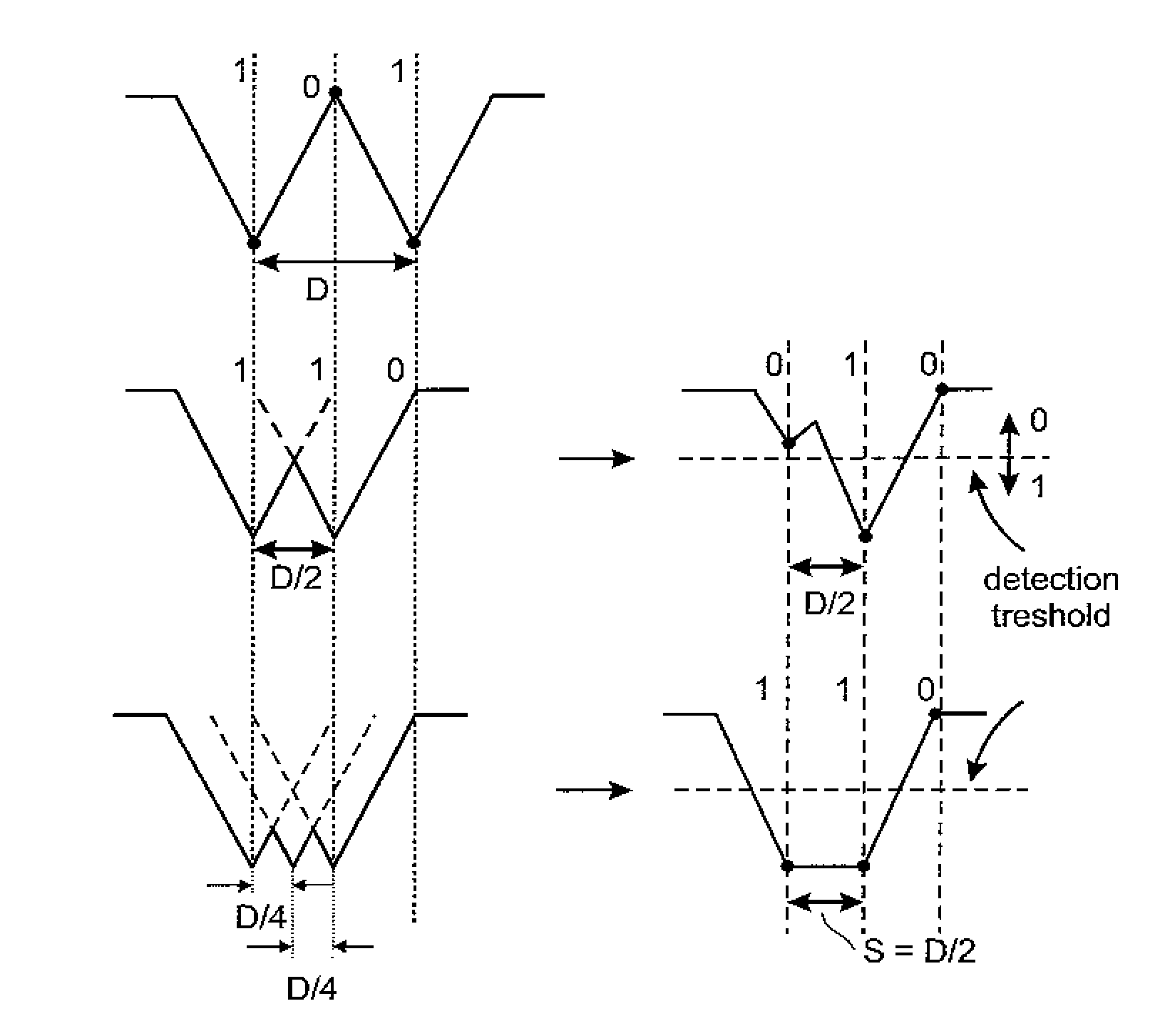
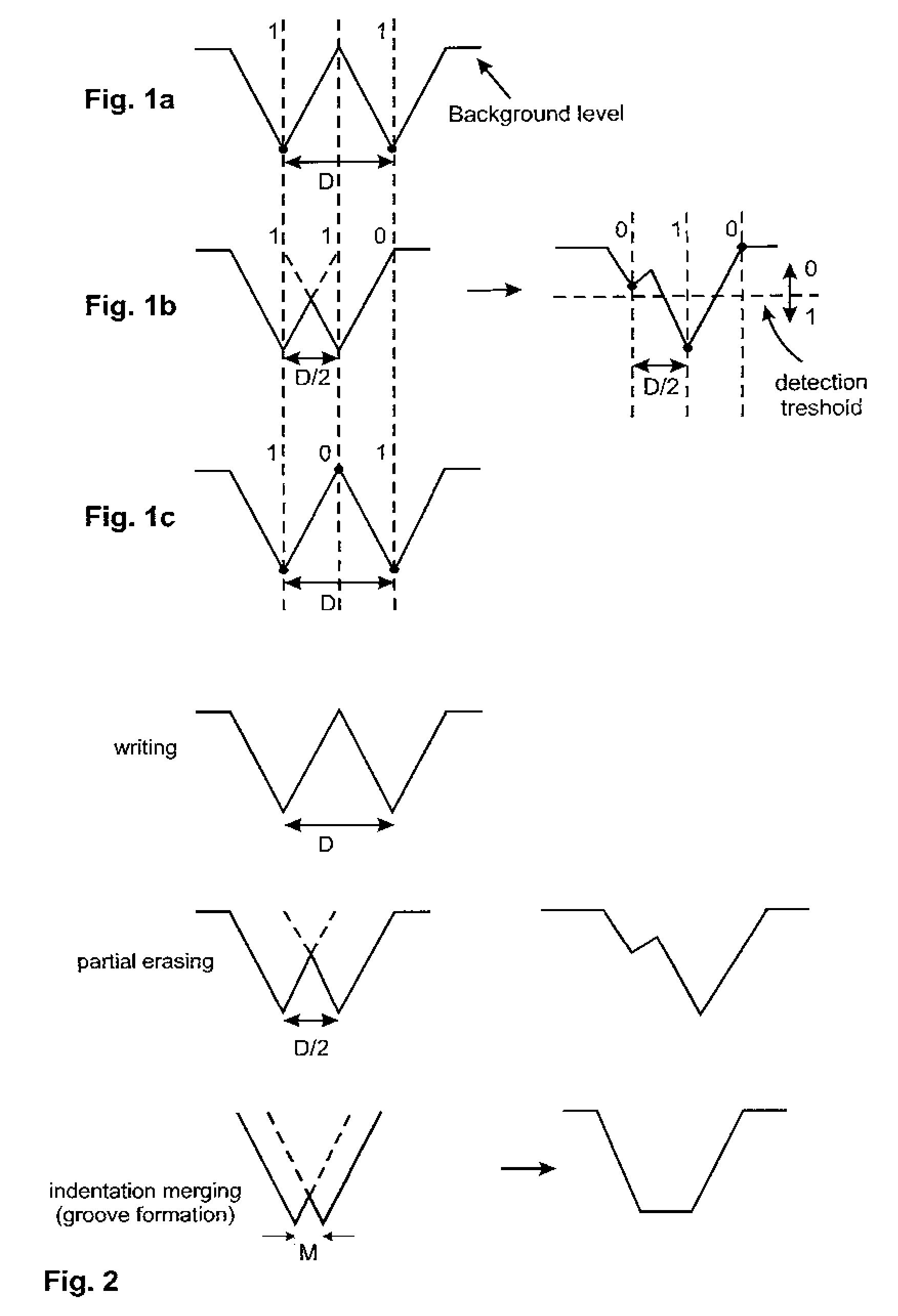
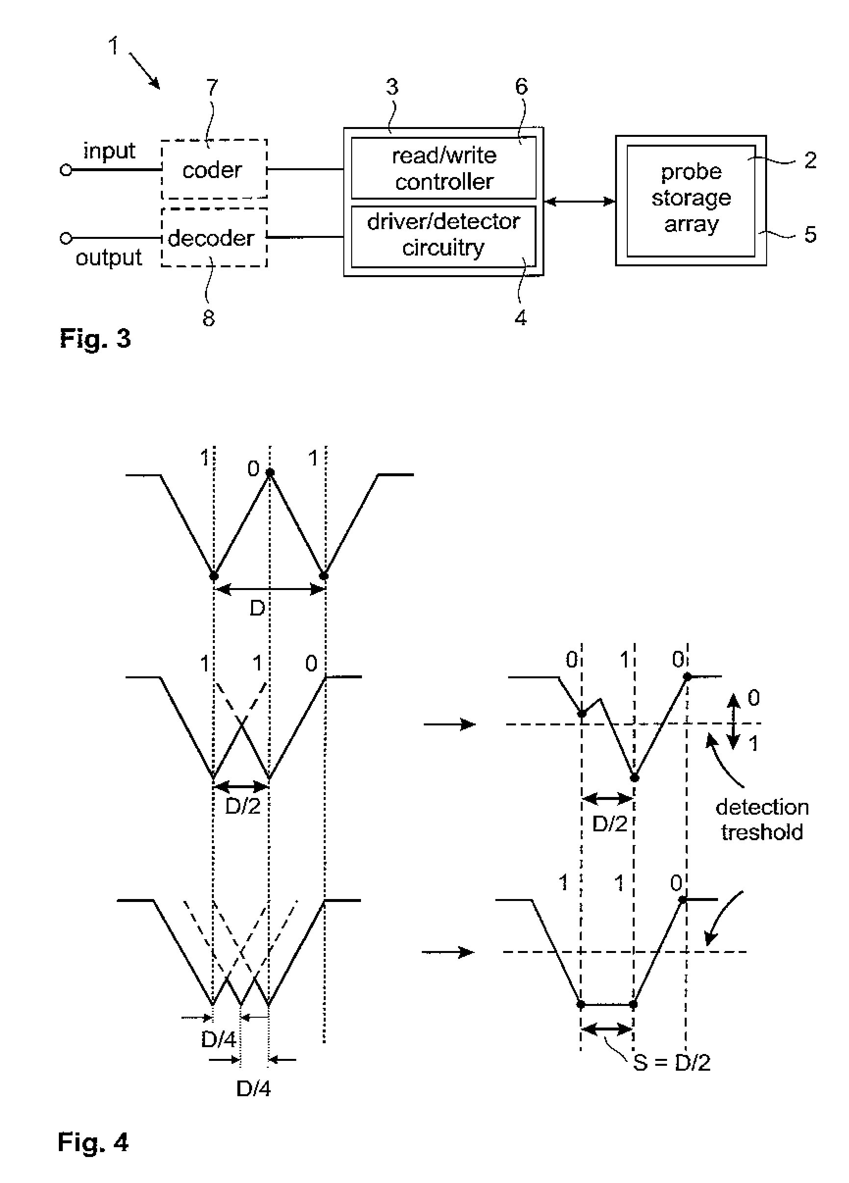
[0036]Before describing operation of an embodiment of the present invention, the principle exploited therein will be explained with reference to FIG. 2. An embodiment of the present invention takes advantage of the fact that thermomechanically-written topographic indentations in polymer films merge into continuous grooves when they are closely spaced spatially. Three different regimes of topographic modification may be distinguished when the spatial distance between the indentations is reduced. In the first regime, where the distance between indentations is at least equal to the indentation interference threshold D, no interference between indentations occurs. This is illustrated in the top diagram in FIG. 2 for an indentation spacing of D. This is the regime in which data writing is typically performed as described earlier with reference to FIGS. 1a and 1c. As already explained, the extent to which the storage density may be increased depends on the threshold D. As soon as the spac...


PUM

PropertyMeasurementUnit
electrostatic voltageaaaaaaaaaa
lengthaaaaaaaaaa
distanceaaaaaaaaaa

Abstract

Methods and apparatus are provided for recording / reproduction of data in a probe-based data storage device (1) in which application of a write signal causes formation of an indentation in a storage surface (5) by a probe of the device (1). Instead of storing information in the presence or absence of indentations on the storage surface as is conventionally done in such devices, information is stored in the form of grooves of variable length separated by lands of variable length. More particularly, a sequence of n>1 successive bits of a first value (typically “1's”) in a recording signal is recorded by applying a series of write signals at respective probe-positions on the storage surface (5). These probe-positions are spaced at w≦M, where M is the indentation merging distance, so that the resulting indentations merge to form a groove in the storage surface (5) spanning n readback sample positions. The readback signal corresponding to the recording signal is sampled at timings corresponding to the readback sample positions to recover the original bit sequence. High density recording is provided because the readback sample position spacing s here satisfies s<D, where D is the indentation interference threshold.

Description

[0001]The present invention relates generally to probe-based data storage devices. Methods, apparatus and computer programs are provided for implementing recording / reproduction techniques offering higher storage densities in these devices.BACKGROUND OF THE INVENTION[0002]In some probe-based data storage devices, the carrier of information is the presence or absence of topographical indentations, or “pits”, on a storage surface. Typically the presence of an indentation corresponds to a bit of value “1” while the absence of an indentation corresponds to a bit of value “0”. Each indentation is formed by application of a write signal which causes a probe of the device to deform the storage surface to create the indentation. For example, in AFM (Atomic Force Microscope)-based storage devices, the probe is a nanometer-sharp tip mounted on the end of a microfabricated cantilever. This tip can be moved over the surface of a storage medium in the form of a polymer film. A single indentation ...

Claims


Application Information

Patent Timeline
Patent Type & Authority Patents(United States)
IPC IPC(8): G11B7/00
CPCB82Y10/00G11B9/14G11B11/007
Inventor ELEFTHERIOU, EVANGELOS S.POZIDIS, CHARALAMPOS
Owner IBM CORP
Why Eureka
Try Eureka