
Method and device for applying fluids

a fluid application and fluid technology, applied in the direction of mechanical vibration separation, additive manufacturing processes, manufacturing tools, etc., can solve the problems of preventing the achievement of smooth surfaces, requiring more frequent maintenance, so as to maximize the angular adjustment accuracy, minimize the time taken by the layering procedure, and achieve the effect of smooth coa

Inactive Publication Date: 2011-02-01
EXONE
View PDF157 Cites 63 Cited by
  • Summary
  • Abstract
  • Description
  • Claims
  • Application Information

AI Technical Summary

Benefits of technology

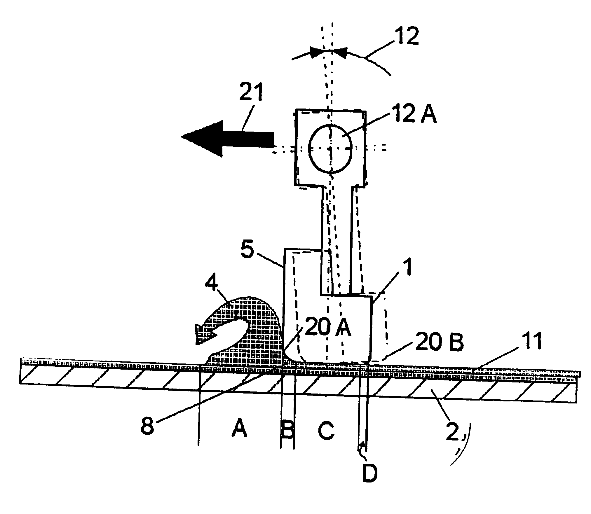
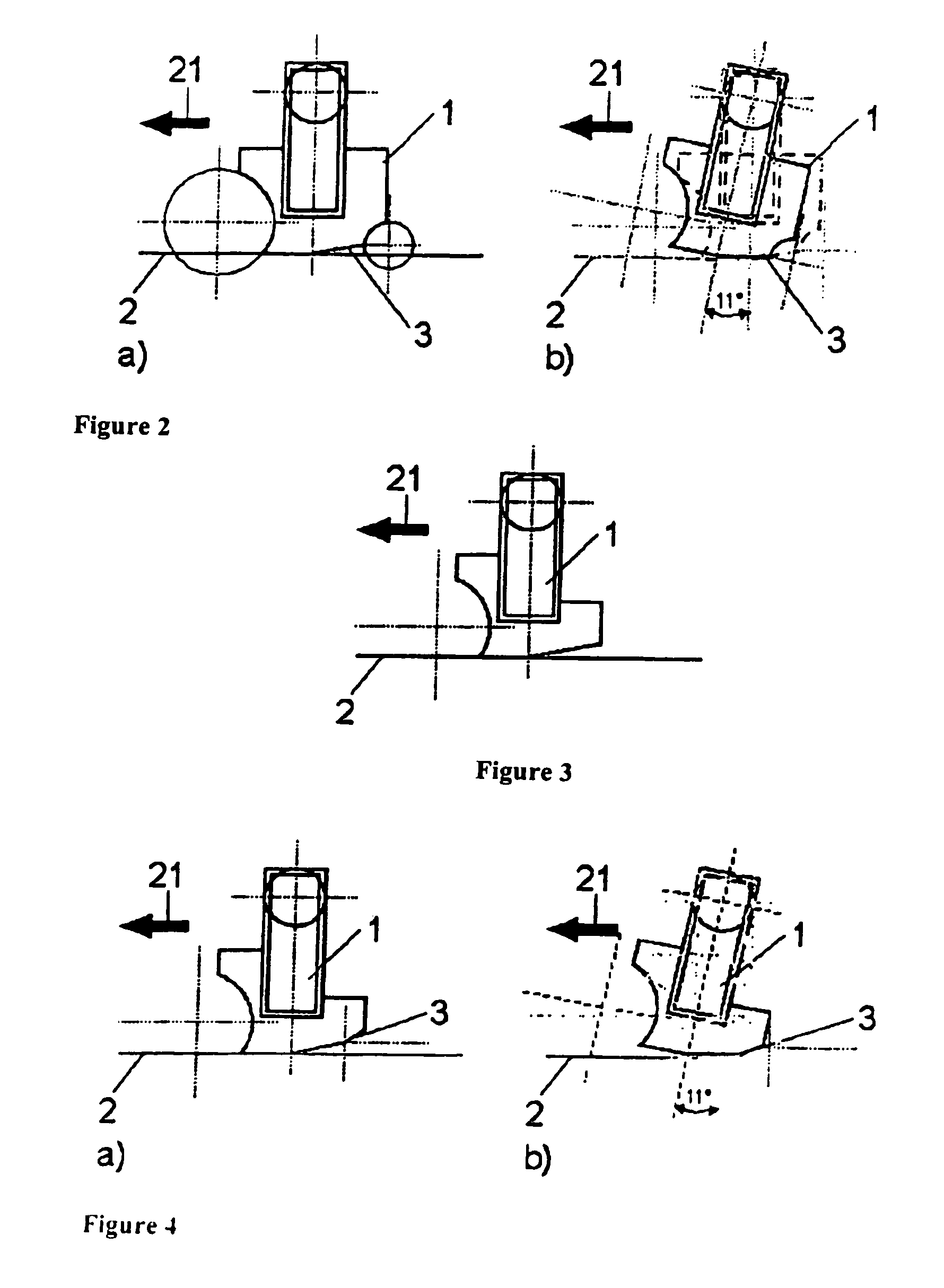
[0030]Furthermore, it proves advantageous to mount the blade such that it oscillates in an angular range between 0.1 and 5°.
[0031]If the blade extends over the entire width or length of the surface to be coated, the time taken by the layering procedure is minimized. End-to-end layering performed simultaneously in this manner also results in a smoother coat.
[0032]If, in a preferred embodiment of t

Problems solved by technology

Difficulties arising during these well-known procedures are often posed by the smoothest and thinnest possible application of particle material; this influences the layer thickness, i.e. the smallest unit and therefore also the accuracy at which the mould can be produced.
However, if such coating techniques involve the use of powders with a strong tendency to form agglomerates, for instance, particle material possessing a very fine grain or a content of binder, it proves very difficult to apply the material in a thin and smooth layer.
The particle material tends to form lumps which stick to the roller, thus preventing achievement of a smooth surface.
Given the use of particle material—especially with a tendency to form lumps—a counter-rotating roller also has the disadvantage of heavily soiling all components which make contact with the particle material, thus entailing more frequent maintenance and proving more expensive.
Similarly, the coating technique described in U.S. Pat. No. 5,730,925 is not capable of achieving smooth surfaces with powders tending to agglomerate, because the powders also form lumps and result in rough surfaces in this case.
This vibrating mechanism also proves disadvantageous, the vertical exertion of force on the particle layer producing an undesirable compression effect which causes uneven compaction of the required mould or model.
This results in uncontrolled displacements in the mould during its fabrication on the powder bed, thus impairing the production accuracy.
Under certain circumstances, particle material with a strong tendency toward agglomeration might even make it completely impossible to produce smooth layers.
The thicker and rougher the layers, the less accurate the shape of the final cast.

Method used


Image

  • Method and device for applying fluids
  • Method and device for applying fluids
  • Method and device for applying fluids

Examples


Embodiment Construction

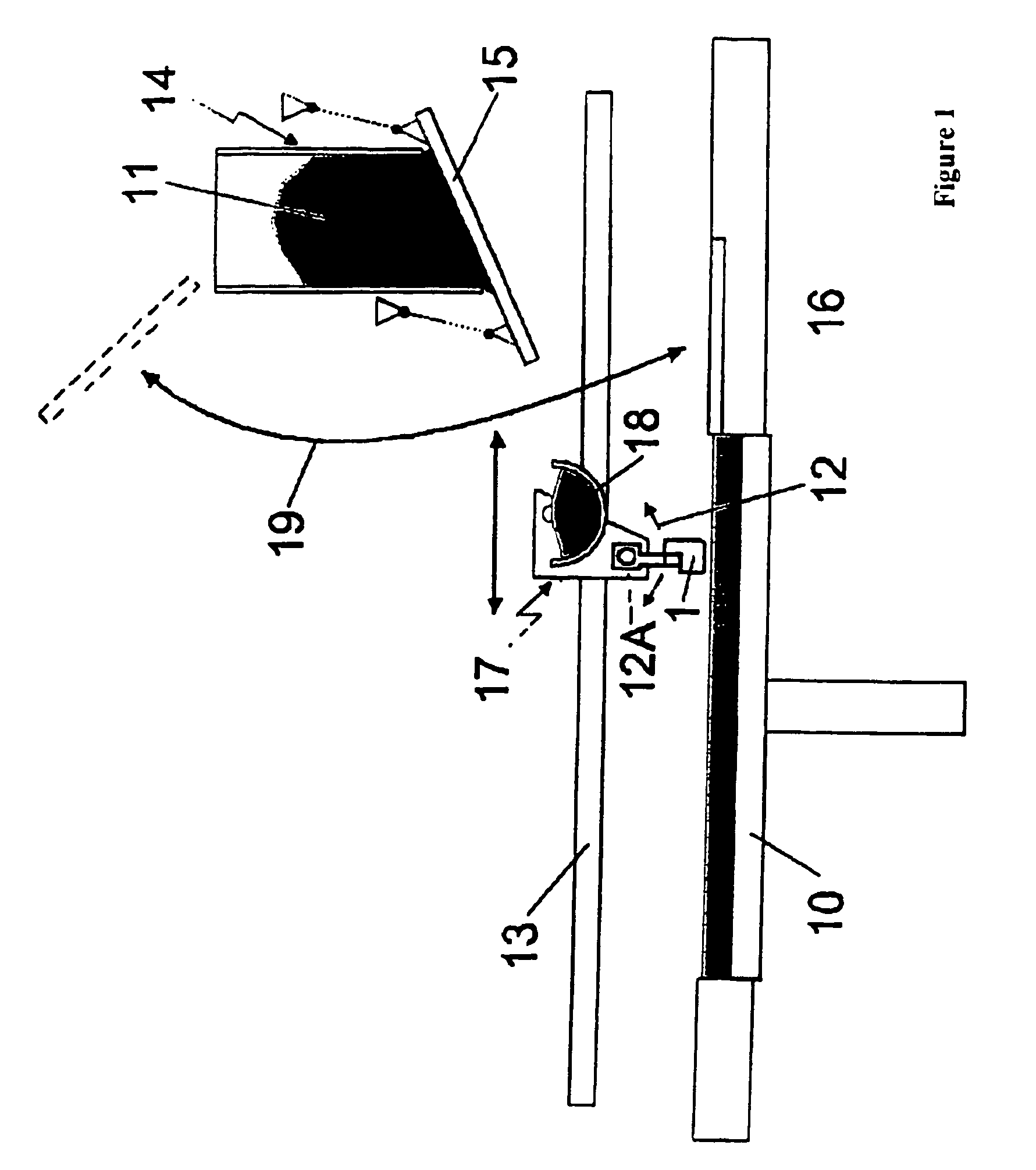
[0049]The procedure and device forming part of the invention are exemplified in a rapid prototyping procedure described in the following and involving a layer-by-layer production of casting patterns using particle material, bonding agent and hardener.

[0050]In particular, the employed mixture of particle material and bonding agent is assumed to exhibit a strong tendency to form lumps, as is usually the case in practice.

[0051]However, the use of such a particle material proves advantageous by eliminating the need for layering the material with binder—a step normally required by the rapid prototyping procedure—and thus making the coating technique faster and more cost-effective.

[0052]Use of the procedure and device forming part of this invention has proven especially beneficial in the case of particle materials possessing a tendency to agglomerate.

[0053]Particle materials with a small / medium grain size of less than 20 μm and wax powder also exhibit a strong tendency to agglomerate.

[005...


PUM

PropertyMeasurementUnit
Thicknessaaaaaaaaaa

Abstract

The invention relates to a method for applying fluids, especially particle material, on a area that is to be coated, wherein the fluid is applied on the area to be coated in front of a blade when observed from the direction of forward movement of the blade and said blade is then displaced on the applied fluid. The method is characterized in that the blade performs an oscillation similar to a rotational movement.

Description

CLAIM OF BENEFIT OF FILING DATE[0001]The present application claims the benefit of the filing date of PCT Application Serial No. PCT / DE02 / 01103, (filed Mar. 26, 2002) (published as WO 02 / 083323) and DE 101 178175.1 (filed Apr. 10, 2001), the contents of which are hereby incorporated by reference in their entirety.FIELD OF THE INVENTION[0002]This invention concerns a procedure and a device for applying fluids in accordance with the general definitions of the independent claims. The invention also concerns the use of such a device.BACKGROUND OF THE INVENTION[0003]In many areas of technology, there is a need to apply fluids—especially those comprising particle material—in thin layers on to a carrier. In many such cases, it is also necessary for the applied layers to have the smoothest possible surface.[0004]For example, a smooth application of particle material to be bonded plays an important role in rapid prototyping procedures.[0005]A rapid prototyping procedure for creating casting ...

Claims


Application Information

Patent Timeline
IPC IPC(8): B05D1/12B05D1/38B28B1/08B05D1/42B05D1/40B05C1/00B05C11/02B05C11/04B29C41/12B29C67/00
CPCB05C11/023B29C67/0077B29C41/12B05D1/42B29C64/153B33Y10/00
Inventor EDERER, INGOHOCHSMANN, RAINERTURCK, HARALD
Owner EXONE
Learn More