
Integral gas turbine compressor and rotary fuel injector

a compressor and gas turbine technology, applied in the field of gas turbine engines, can solve the problems of high centrifugal force and high fuel pressure, and achieve the effects of improving combustion, high fuel pressure, and rapid and effective fuel atomization

Inactive Publication Date: 2011-03-01
FLORIDA TURBINE TECH
View PDF18 Cites 15 Cited by
  • Summary
  • Abstract
  • Description
  • Claims
  • Application Information

AI Technical Summary

Benefits of technology

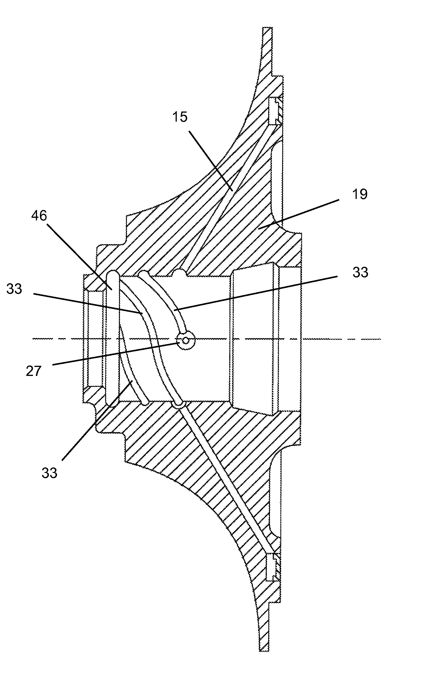
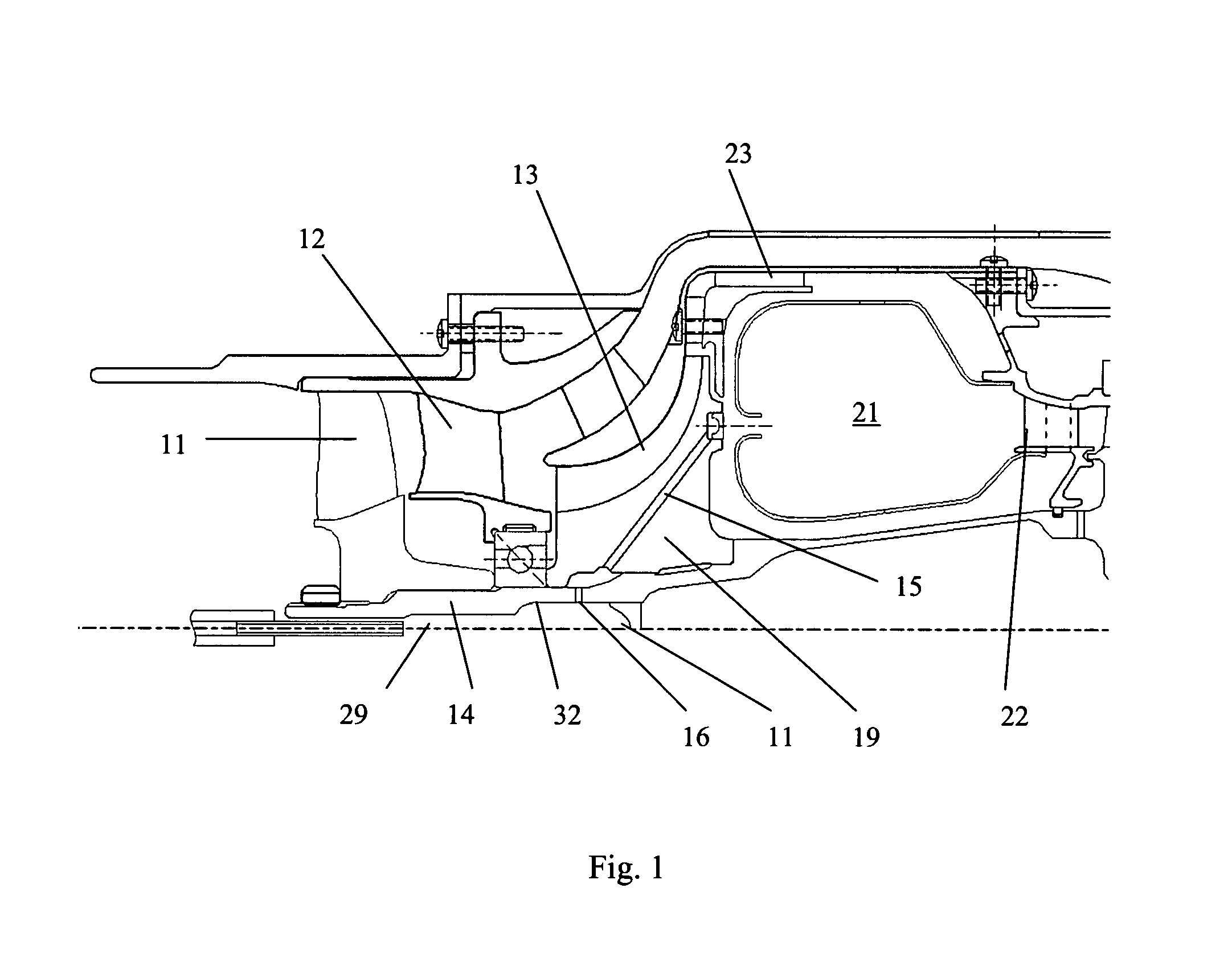
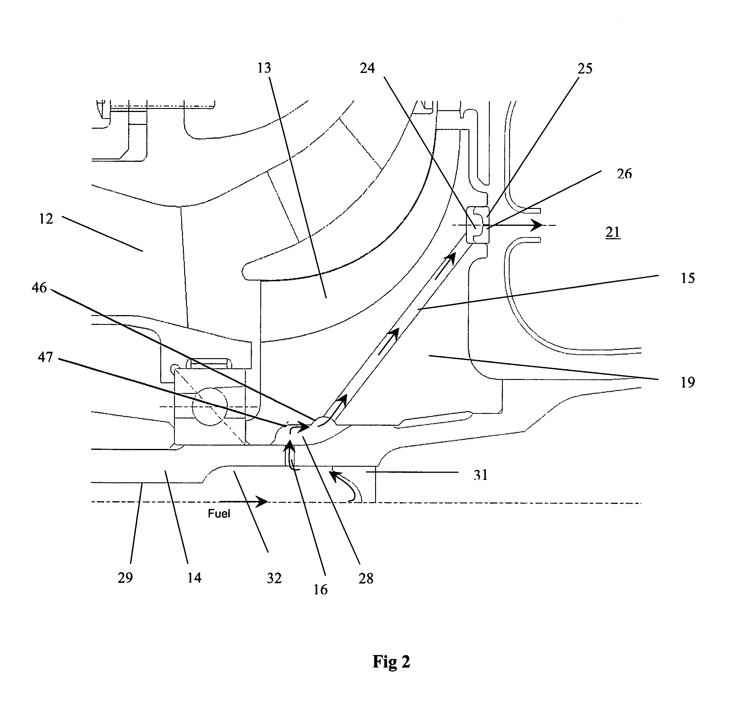
[0013]In a gas turbine engine, an integral centrifugal compressor and fuel injector in which a fuel is introduced into a bore of the impeller and passes into a plurality of fuel passages extending substantially in a radial direction such that rotation of the impeller also pressurizes the fuel within the passages. At the end of the passages are fuel nozzle inserts that inject the pressurized fuel in an axial direction into the combustor. Because the integral impeller and fuel injector is rotating during operation, a uniform circumferential distribution of fuel is sprayed into the combustor. The very high centrifugal forces produce a very high fuel pressure. The high delta pressure across the fuel nozzles produces a rapid and effective fuel atomization and improved combustion. Fuel is channeled along the bore through helical grooves and into the radial passages such that the mass imbalance inherent in the rotor can be counteracted by the distribution of more fuel to the fuel passages opposite to the imbalance so that the rotor is more balanced.

Problems solved by technology

The very high centrifugal forces produce a very high fuel pressure.

Method used


Image

  • Integral gas turbine compressor and rotary fuel injector
  • Integral gas turbine compressor and rotary fuel injector
  • Integral gas turbine compressor and rotary fuel injector

Examples


second embodiment

[0025]As seen in FIG. 3, the inner radius (ri) of the fuel column within the passage 15 controls the fuel pressure which controls the fuel flow rate and thus the rotor speed. An engine controller would sense the rotor speed and increase or decrease the fuel flow until a desired inner radius (i.e. rotor speed) is achieved. At maximum power with the fuel at 4,900 psi and a fuel ejection speed of Mach 2.6, effective fuel atomization is achieved. At idle flow rates, the inner radius—and thus the fuel pressure—must be rather low since flow rate is driven by pressure. This could result in atomization and ignition issues during start-up. The present invention uses four nozzles. The fuel pressure can be increased by a factor of 4 or 5 if the flow is split between two sets of fuel nozzles. This is easily achieved by staging the fuel delivery. FIG. 4 shows the present invention that will achieve this objective. The fuel introduced into the bore of the impeller would first pool in a forward or...

first embodiment

[0028]FIGS. 7 and 8 show the helical grooves 33 that feed the low pressure fuel to the radially directed fuel passages 15 and the nozzles. In the present invention, there are four nozzles spaced about the rotor disk at about 90 degrees each. Each nozzle 25 is connected to a separate radial fuel passage 15, and each radial fuel passage 15 is connected to a separate helical groove 33 formed within the rotor disk 19. Each helical groove 33 extends from the spherical openings 27 and coils 180 degrees around the rotor disk before entering the bore fuel collection groove 46. FIG. 6 shows a schematic representation of this with two nozzles and two radial fuel passages each with a helical groove extending 180 degrees from the radial fuel passage entrance. As seen in FIG. 6, the helical passages supply fuel 180 degrees away from the imbalance vector.

[0029]The impeller and fuel injector of FIG. 1 operates as follows. Fuel is introduced into the bore of the impeller and centrifuged outward thr...


PUM


Abstract

An integral impeller and fuel pump for a small gas turbine engine, the impeller being a centrifugal impeller to supply compressed air to the combustor, the rotor disk of the centrifugal compressor having at least one radial fuel passage connecting a central bore of the rotor disk to a fuel nozzle located on the rear face of the rotor disk. A low pressure fuel supplied by a small pump delivers the fuel to the central bore where the fuel is collected within helical grooves and channeled into the radial fuel passages where the fuel is pressurized to a relatively high pressure due to the high rotational speed of the centrifugal compressor. Highly compressed fuel is injected into the combustor through fuel nozzles in an axial direction as the rotor disk rotates. Helical grooves in the central bore each connected to a radial fuel passage move the fuel to an opposite side of the central bore to counteract rotor imbalance. In another embodiment, a primary annular groove collects fuel and, at a low speed, passes all of the fuel to a first radial fuel passage into a first fuel nozzle such that only some of the fuel nozzles inject fuel into the combustor. At a higher speed, some of the fuel collected in the primary annular groove is spilled over into a secondary annular groove that passes the spilled-over fuel into a second radial passage and second fuel nozzle such that all of the fuel nozzles inject fuel into the combustor.

Description

BACKGROUND OF THE INVENTION[0001]1. Field of the Invention[0002]The present invention relates generally to a gas turbine engine, and more specifically to an integral compressor and centrifugal fuel pump.[0003]2. Description of the Related Art Including Information Disclosed Under 37 CFR 1.97 and 1.98[0004]A small gas turbine engine operates at a very high rotational speed because of its size. A fuel is mixed in the combustor with pressurized air and burned to produce a hot gas flow which is then passed through the turbine to drive the compressor and a bypass fan if used. Some prior art engines use a plurality of individual fuel injectors spaced around the combustor and inject fuel directly into the combustor. Enough injectors are required so that a fairly even combustion pattern is created within the combustor. Using many injectors will also increase the cost and complexity of the engine.[0005]Some prior art small gas turbine engines use a slinger to compress and sling the fuel into...

Claims


Application Information

Patent Timeline
Patent Type & Authority Patents(United States)
IPC IPC(8): F02C1/00F01D5/14F03B3/12F02C7/22
CPCF01D5/048F02C3/08F02C7/22F02C7/222F04D29/284F05D2250/25F05D2250/80
Inventor EWING, JR., JOSEPH H.
Owner FLORIDA TURBINE TECH
Learn More