
Metallic coils enlaced with biological or biodegradable or synthetic polymers or fibers for embolization of a body cavity

a technology of biodegradable or biodegradable polymers or fibers and metal coils, which is applied in the field of vasoocclusion devices, can solve the problems of no efficacy data for coated coils, no better than bare metal coils, and recurrence of aneurysms, etc., and achieves the effect of increasing the effective surface area and more surface area

Active Publication Date: 2011-03-01
COVIDIEN LP
View PDF95 Cites 72 Cited by
  • Summary
  • Abstract
  • Description
  • Claims
  • Application Information

AI Technical Summary

Benefits of technology

[0013]A need exists for an embolic device that can increase the effective surface area so that higher levels of biological, biodegradable, or synthetic agents can be present to embolize a body cavity and direct or provoke a healing response.
[0014]We sought to provide more surface area to an embolic coil device by adding fibers. By increasing initial blood contact surface area between aneurismal blood and tissue, bioactive agents (biological, biodegradable, or synthetic) can be used at higher concentrations or in greater amounts than previously used. The same concentration or amount can be spread over a larger contact surface area.

Problems solved by technology

Due to insufficient healing at the aneurysm / parent artery interface, mechanical and biological forces, incompletely understood, create a new expansion of aneurysm.
Thus the aneurysm recurs and remains susceptible to rupture and hemorrhagic stroke.
Both approaches suffer from the same problem: they are limited by the small size of these coils and the fact that the coils must be delivered through a microcatheter with the smallest ID of ˜0.015″.
Limited to no efficacy data exist for the coated coils.
However, physician feedback indicates that the results are no better than bare-metal coils.

Method used


Image

  • Metallic coils enlaced with biological or biodegradable or synthetic polymers or fibers for embolization of a body cavity
  • Metallic coils enlaced with biological or biodegradable or synthetic polymers or fibers for embolization of a body cavity
  • Metallic coils enlaced with biological or biodegradable or synthetic polymers or fibers for embolization of a body cavity

Examples


example 1

Adding Fibers

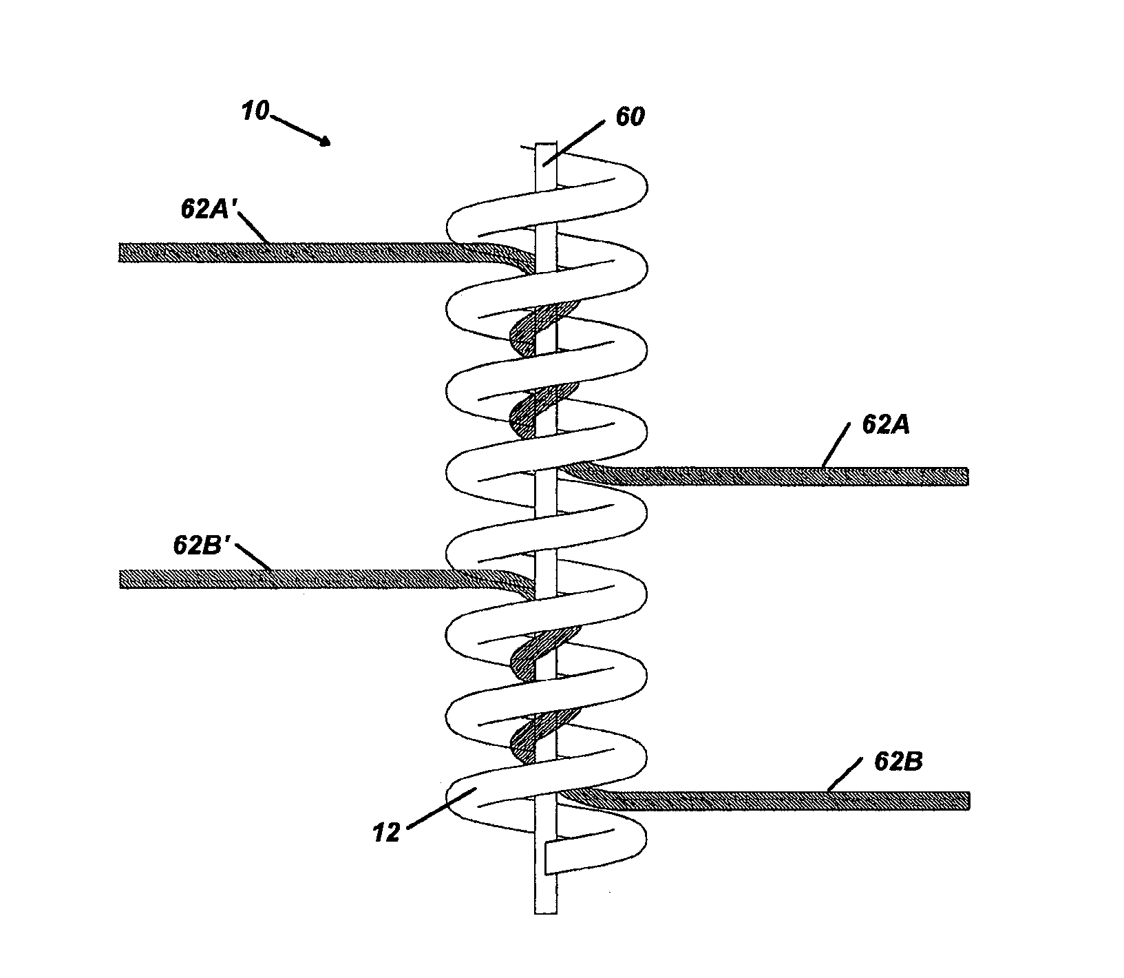
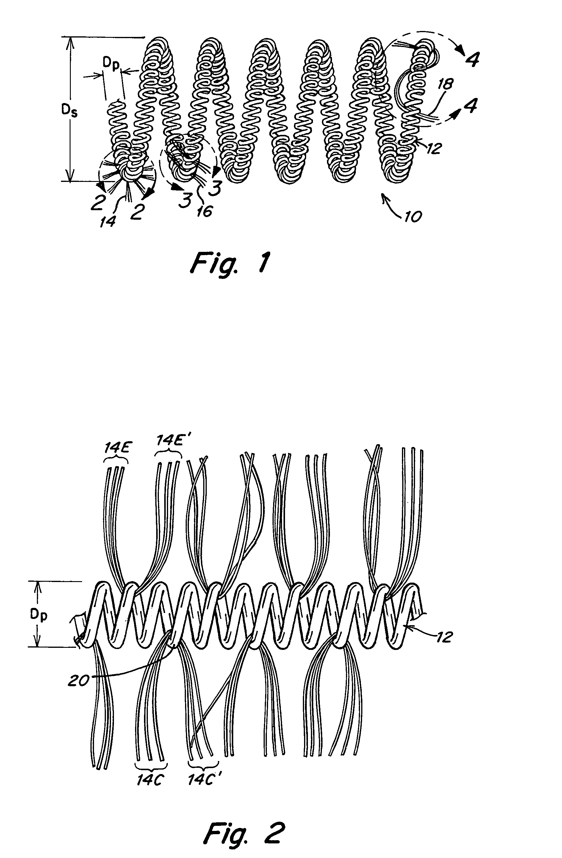
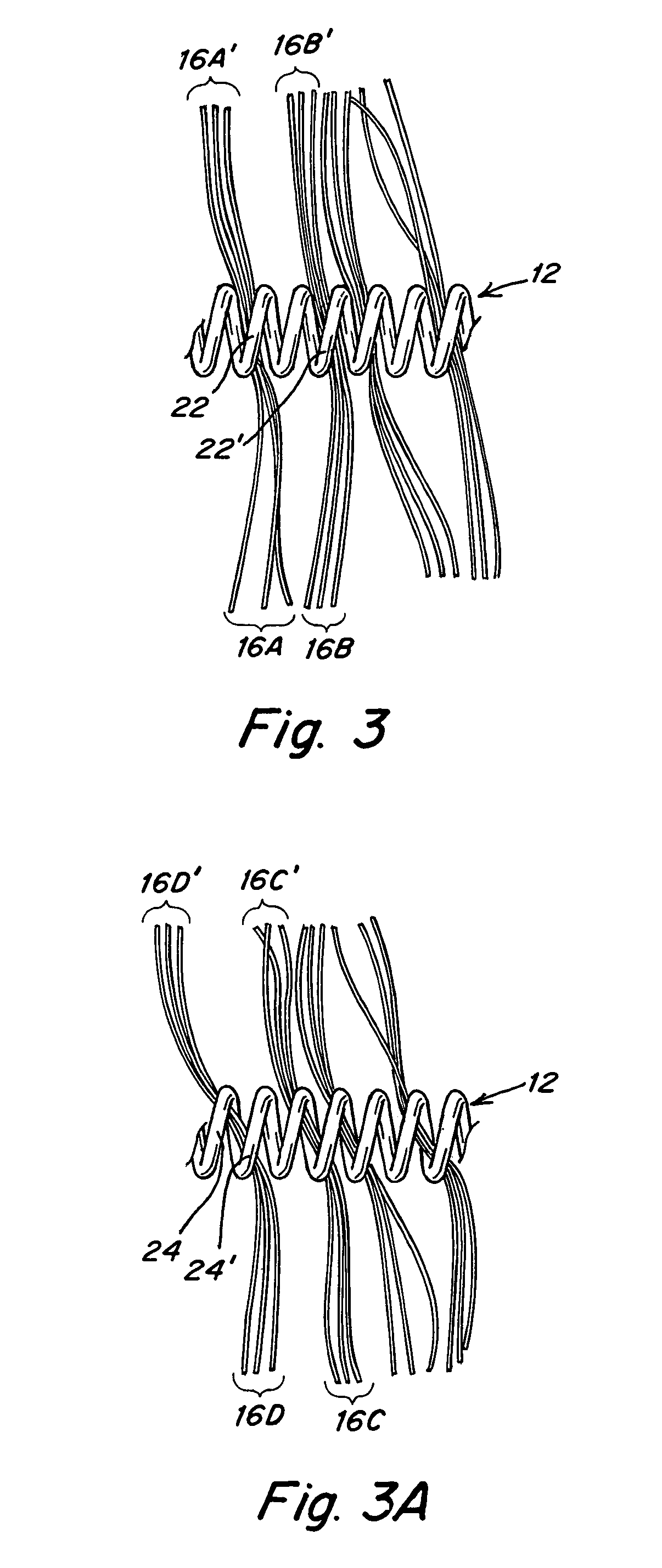
[0082]A T-10 platinum coil is obtained and fastened to a flat surface at its ends. It has a primary helix diameter of 0.028 mm. A plurality of Vicryl 90 / 100 PGLA sutures with diameters of from 0.099 mm to 0.029 mm are obtained. These sutures are made up of a bundle of 6-7 small microfibers about 12 μm in diameter. A single monofilament of similar size could also be employed. The fibers are cut into about 2 cm lengths and physically enlaced in between windings of the T-10 coil in the configurations shown in FIGS. 2-5. This is done until a total of about 10-20 fibers per cm extend away from the coils. The fibers are trimmed to have 2-4 cm lengths extending from the coils.

[0083]If the fibers are coated with bioactive material or if they contain bioactive material, the surface area provided by the fibers would enhance delivery and activity.

example 2

Coating

[0084]1. Fill an ice container with cold water and add ice as needed to reach a temperature of 4-6° C.

[0085]2. Submerge a 15 ml centrifuge tube rack into the container / bucket.

[0086]3. Place 15 ml centrifuge tubes (filled with collagen solution at pH 7.4±2) into the centrifuge rack

[0087]4. Pass a platinum coil through a drilled centrifuge cap into the solution.

[0088]5. Allow the coil to remain in the solution for 20 minutes.

[0089]6. Remove the coil and tube (ensure that the coil remains in the collagen solution) from the ice container / bucket.

[0090]7. Place the coil(s) in a 37° C. oven for 4 hours.

[0091]8. Remove the coil from the collagen solution and rinse the coil 3× in PBS and 3× in distilled water.

[0092]9. Allow the coated coil to dry overnight.


PUM

PropertyMeasurementUnit
lengthaaaaaaaaaa
lengthaaaaaaaaaa
diameteraaaaaaaaaa

Abstract

The invention provides for vaso-occlusive coils comprising fibers.

Description

[0001]This application claims priority to Provisional Application No. 60 / 573,710 filed May 21, 2004 which is incorporated by reference in its entirety.FIELD OF THE INVENTION[0002]This invention relates to vaso-occlusion devices for forming an occlusion (embolism) at a desired vascular location, in particular at the site of an aneurism. The devices are helical wire coils preferably with enlaced fibrous materials providing an increased surface area to facilitate high rates of desired bioactions such as bioactive material release or embolic interactions between the device's surface and the patient's bloodstream. The coils may be coated with at least a single layer including a bioactive material.BACKGROUND[0003]Body cavity embolism (e.g. brain blood vessel aneurysm occlusion by detachable coils, liquid embolism, particle embolism, balloon embolism) is a treatment that may have a high incidence of recurrence. Due to insufficient healing at the aneurysm / parent artery interface, mechanical...

Claims


Application Information

Patent Timeline
Patent Type & Authority Patents(United States)
IPC IPC(8): A61M29/00A61B17/00A61B17/12A61L31/02A61L31/10A61L31/12A61L31/16
CPCA61B17/12022A61B17/12109A61B17/12113A61B17/12145A61B17/1215A61B17/12154A61L31/022A61L31/10A61L31/128A61L31/16A61L31/18A61B2017/00004A61B2017/00526A61L2300/606A61L2430/36
Inventor PATTERSON, WILLIAM R.SLEE, EARLWILDER, TOMMCCARTHY, THOMASSTRAUSS, BRIANMONSTADT, HERMANHENKES, HANS
Owner COVIDIEN LP
Learn More