Electrolytic cell and system for treating water

a technology of electrolysis cell and water treatment system, which is applied in the direction of flow mixer, chemical/physical process, energy-based wastewater treatment, etc., can solve the problems of inefficient existing system, large amount of energy, and need constant monitoring and frequent maintenance of existing chlorine generation system

Active Publication Date: 2011-03-01
UGSI SOLUTIONS INC
View PDF11 Cites 31 Cited by
  • Summary
  • Abstract
  • Description
  • Claims
  • Application Information

AI Technical Summary

Benefits of technology

[0022]Generally, the inner electrode plates are passively charged via conduction of the base solution such that they function as bipolar electrodes. The electrode plates may be configured to liberate hydrogen from a base solution of salt and water, resulting in generation of sodium hypochlorite. The plates may also be configured to liberate hydrogen from a base solution of water to generate oxygen to oxidize the water. The electrode plates are coated with varying catalytic materials such as DSA or platinum to facilitate the reaction for different base solutions.

Problems solved by technology

However, existing systems are inefficient, requiring large amounts of energy to produce the amounts of chlorine required.
In addition, existing chlorine generation systems require constant monitoring and frequent maintenance from material buildup in the system.
These systems typically utilize phase angle-fired SCR control of the rectification process, which account for the vast majority, if not all, of the failures related to the D.C. rectification process.
The water storage systems currently used to hold treated water also have drawbacks.
These large water reservoirs are prone to water quality problems as they are typically stagnant with as little as one to two percent turnover per day.
These factors can all compound to produce a poor or even unhealthy water quality leading to consumer complaints and related water quality issues within the distribution system.

Method used


Image

  • Electrolytic cell and system for treating water
  • Electrolytic cell and system for treating water
  • Electrolytic cell and system for treating water

Examples


Embodiment Construction

[0068]Referring more specifically to the drawings, for illustrative purposes the present invention is embodied in the apparatus generally shown in FIG. 1 through FIG. 13. It will be appreciated that the apparatus may vary as to configuration and as to details of the parts, and that the method may vary as to the specific steps and sequence, without departing from the basic concepts as disclosed herein.

[0069]1. Sodium Hypochlorite Generation and Storage

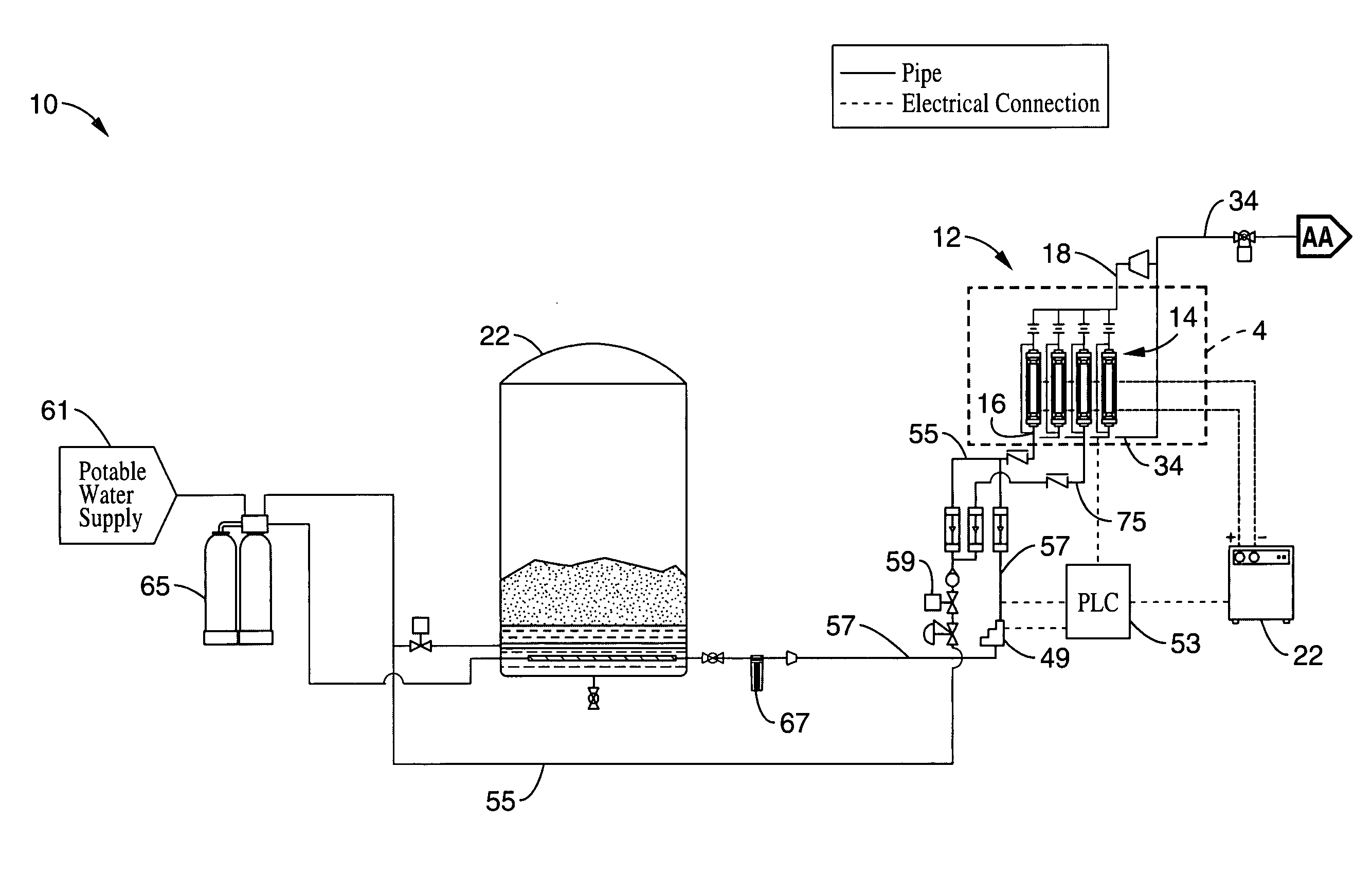
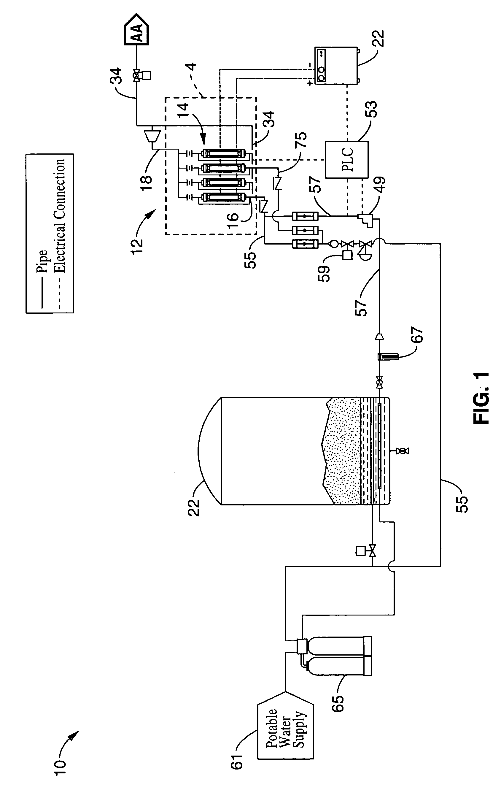
[0070]Referring to FIG. 1, an on-site sodium hypochlorite system 10 is disclosed. The sodium hypochlorite system 10 is configured to produce a weak bleach solution from a base solution of ordinary salt, water and electrical power. The process typically outputs a sodium hypochlorite solution, e.g. “bleach,” having a concentration in the range of 0.8-1.0% available chlorine. As a reference, household bleach such as Clorox is typically 5-6%, while liquid pool chlorine is 12-13%.

[0071]Solar grade salt is first dissolved with water a potable...


PUM

PropertyMeasurementUnit
voltageaaaaaaaaaa
voltageaaaaaaaaaa
volumesaaaaaaaaaa

Abstract

A water treatment system is disclosed having electrolytic cell for liberating hydrogen from a base solution. The base solution may be a solution of brine for generating sodium hypochlorite, or potable water to be oxidized. The cell has first and second opposing electrode endplates held apart from each other by a pair of supports such that the supports enclose opposing sides of the endplates to form a cell chamber. One or more inner electrode plates are spaced apart from each other in the cell chamber in between the first and second electrode plates. The supports are configured to electrically isolate the first and second electrode plates and the inner electrode plates from each other. The first and second electrode plates are configured to receive opposite polarity charges that passively charge the inner electrode plates via conduction from the base solution to form a chemical reaction in the base solution as the base solution passes through the cell chamber.

Description

CROSS-REFERENCE TO RELATED APPLICATIONS[0001]This application claims priority from U.S. Provisional Application Ser. No. 60 / 689,607, filed on Jun. 10, 2005, incorporated herein by reference in its entirety.STATEMENT REGARDING FEDERALLY SPONSORED RESEARCH OR DEVELOPMENTNot ApplicableINCORPORATION-BY-REFERENCE OF MATERIAL SUBMITTED ON A COMPACT DISCNot ApplicableNOTICE OF MATERIAL SUBJECT TO COPYRIGHT PROTECTION[0002]A portion of the material in this patent document is subject to copyright protection under the copyright laws of the United States and of other countries. The owner of the copyright rights has no objection to the facsimile reproduction by anyone of the patent document or the patent disclosure, as it appears in the United States Patent and Trademark Office publicly available file or records, but otherwise reserves all copyright rights whatsoever. The copyright owner does not hereby waive any of its rights to have this patent document maintained in secrecy, including withou...

Claims


Application Information

Patent Timeline
Patent Type & Authority Patents(United States)
IPC IPC(8): C25B9/18B01F25/60C25B9/17
CPCC02F1/4672C25B1/26C25B9/063C25B9/203C02F1/685C02F1/686B01F5/0068B01F5/0206G01N1/2035B01F2005/0002C02F1/4696C02F1/5227C02F1/5236C02F2001/46128C02F2001/46142C02F2201/4611C02F2201/46125C02F2201/46145C02F2201/4618C02F2201/46185C02F2209/005C02F2209/29Y02E60/366C02F1/001B01F2005/004C02F1/4674Y02W10/37Y02E60/36C25B11/036C25B9/75B01F25/21B01F25/104B01F2025/91B01F2025/9191C02F1/68C02F2201/461
Inventor SIMMONS, BRENT A.THORDARSONN, GUNNAR T.ROBERTSON, JAMES C.
Owner UGSI SOLUTIONS INC
Why Eureka
Try Eureka