
Slot resonance coupled standing wave linear particle accelerator

a standing wave and particle accelerator technology, applied in accelerators, klystrons, electric discharge tubes, etc., can solve the problems of large and more complex high-energy linear accelerators, small mode separation, and disturbance of the synchronism between particle beams and standing waves, so as to optimize the timing and effectiveness of alternating electric fields

Inactive Publication Date: 2011-03-01
FARTECH
View PDF26 Cites 12 Cited by
  • Summary
  • Abstract
  • Description
  • Claims
  • Application Information

AI Technical Summary

Benefits of technology

"The present invention provides a linear particle accelerator that uses a standing electromagnetic wave to accelerate charged particles. The accelerator includes an elongate hollow accelerator body with a series of transverse interior walls spaced apart to form resonant cavities. The accelerator body has an input port for introducing a high power radiofrequency input signal that maintains the standing wave. The charged particles are introduced at one end of the accelerator and emitted at the other end. The accelerator is designed to synchronize the standing wave with the charged particles as they pass through the resonant cavities, allowing for effective acceleration. The accelerator also includes a slot system with alternating resonant and non-resonant slots to optimize the timing and effectiveness of the accelerating field. The technical effects of the invention include improved acceleration of charged particles and synchronization of the standing wave with the particles as they pass through the resonant cavities."

Problems solved by technology

High energy linear accelerators, known as linacs, are larger and more complex, typically ranging from approximately one meter to several kilometers in length.
Nevertheless, the problem with a 0 or π mode structure is that the dispersion curve at both 0 and π has a slope of zero, so the mode separation is very small.
Furthermore, excitation of undesired modes disturbs the desired electric field pattern and changes the way the particles absorb energy, and thus disturb the synchronism between the particle beam and the standing waves.
Although DTL-based proton acceleration linacs have been used for many years, they are relatively bulky and difficult to service.
They require a different RF power source than the higher energy segments of the accelerator, and are expensive to fabricate because of the need to incorporate quadrupole magnet focusing cells within the drift tubes.

Method used


Image

  • Slot resonance coupled standing wave linear particle accelerator
  • Slot resonance coupled standing wave linear particle accelerator
  • Slot resonance coupled standing wave linear particle accelerator

Examples


Embodiment Construction

[0042]The present invention provides a linear standing wave particle accelerator having a series of resonant accelerating cells connected by slots, at least some of which slots are sized and shaped so as to be resonant at a frequency comparable to that of the accelerating cells.

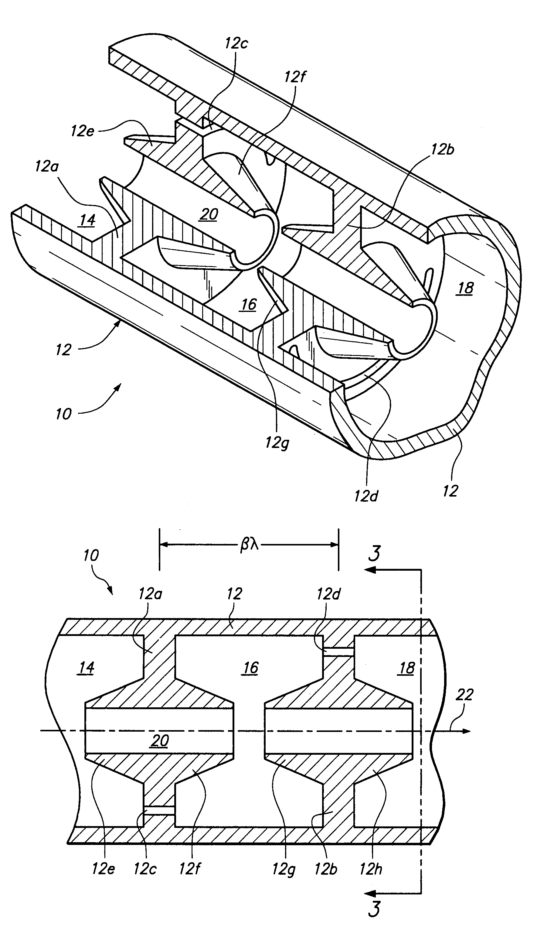
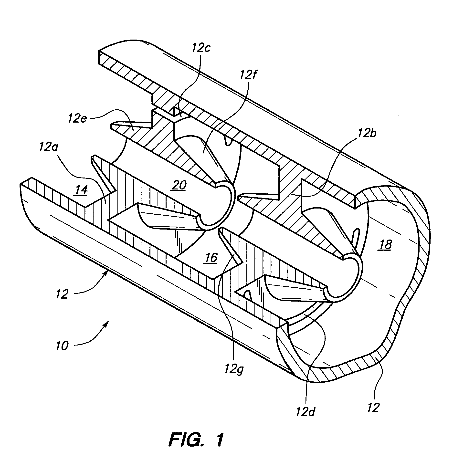
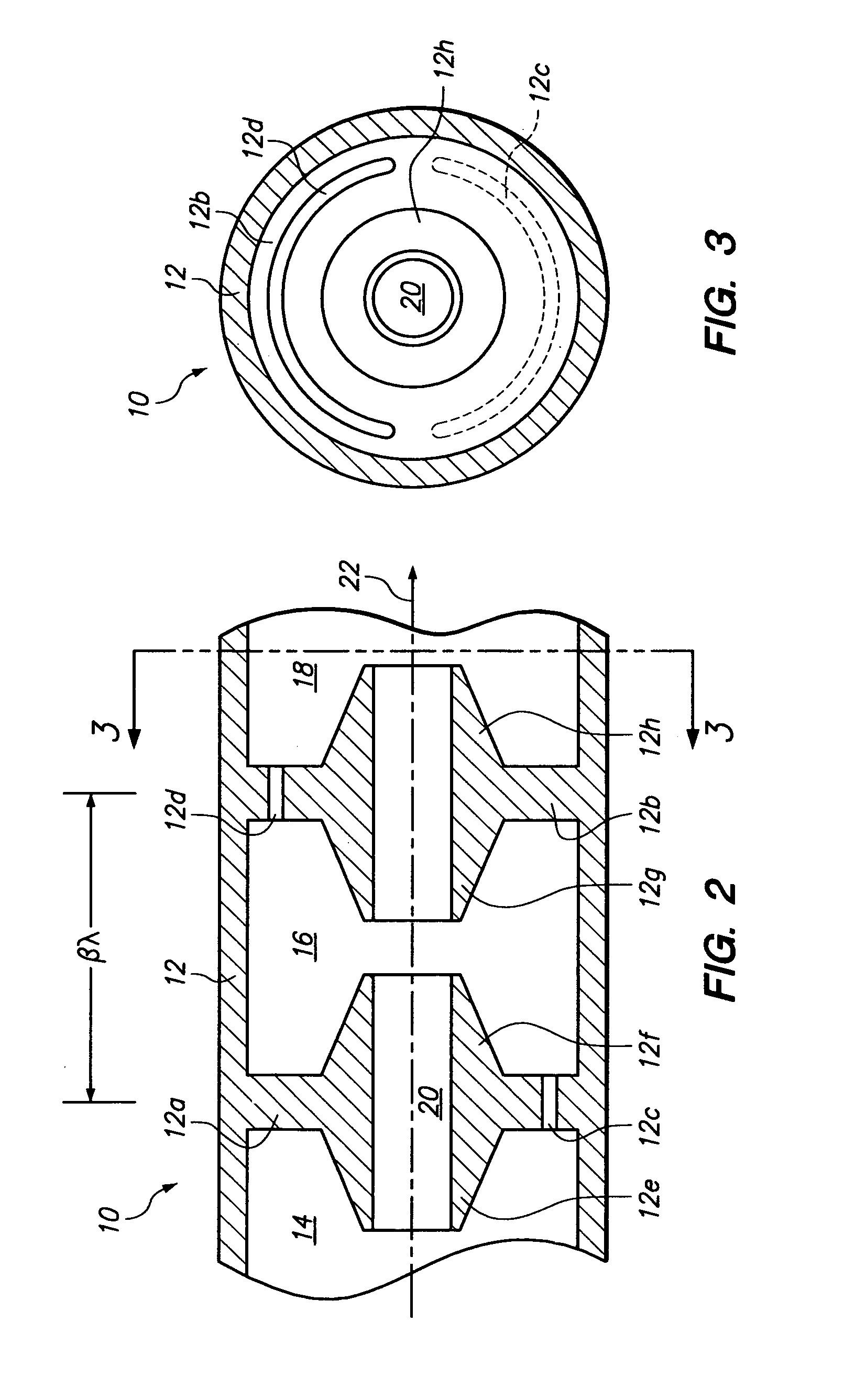
[0043]FIGS. 1 through 3 illustrate a segment 10 of a linear standing wave accelerator constructed in accordance with a first preferred embodiment of the present invention, which is referred to herein as “biperiodic” for reasons explained below. The segment 10 includes a cylindrical copper accelerator tube 12 having transverse interior walls 12a and 12b, which together partially define three successive accelerating cells, or cavities, 14, 16 and 18 (additional interior walls adjacent cavities 14 and 18 are not shown). Cells 14 and 16 share a common interior wall 12a, and cells 16 and 18 share common interior wall 12b.

[0044]While the terms “cell” and “cavity” are generally used interchangeably herein, the term...


PUM


Abstract

A slot resonance coupled, linear standing wave particle accelerator. The accelerator includes a series of resonant accelerator cavities positioned along a beam line, which are connected by resonant azimuthal slots formed in interior walls separating adjacent cavities. At least some of the slots are resonant at a frequency comparable to the resonant frequency of the cavities. The resonant slots are offset from the axis of the accelerator and have a major dimension extending in a direction transverse to the radial direction with respect to the accelerator axis. The off-axis resonant slots function to magnetically couple adjacent cavities of the accelerator while also advancing the phase difference between the standing wave in adjacent cavities by 180 degrees in addition to the 180 degree phase difference resulting from coupling of the standing wave in each cavity with the adjacent slot, such that the signals in each cavity are in phase with one another and each cavity functions as a live accelerating cavity. The resonance frequency of the slot is the comparable to the resonance frequency of the cavities, resulting in coupling of the cavities while also eliminating the need for side-cavity or other off-axis coupling cavities.

Description

BACKGROUND OF THE INVENTION[0001]The invention disclosed and claimed herein is related to high energy linear charged particle accelerators of the kind used to accelerate protons, electrons or ions.[0002]Linear particle accelerators are used to produce beams of electrically charged nuclear or atomic particles. Low energy linear particle accelerators include cathode ray tubes, x-ray generators, and other similar devices. High energy linear accelerators, known as linacs, are larger and more complex, typically ranging from approximately one meter to several kilometers in length.[0003]Linear accelerators are used in medicine for radiotherapy purposes and in industry as testing electron accelerators and for other purposes. They are also used in high energy nuclear physics research. Proton accelerators, for example, are used as drivers for neutrino experiments and as spallation neutron sources, and are of potential use in driving and controlling sub-critical nuclear reactors. Another poten...

Claims


Application Information

Patent Timeline
Patent Type & Authority Patents(United States)
IPC IPC(8): H05H9/00
CPCH05H7/22H05H9/04
Inventor MILLER, ROGER H.BAROV, NIKOLAI
Owner FARTECH
Learn More