
Recording and displaying logic circuit simulation waveforms

a logic circuit and simulation waveform technology, applied in the field of simulation of electronic logic circuits, can solve the problems of waveform display tools that crash in use, the size of vcd format files is often prohibitively large to be handled by waveform display tools, and the large amount of recorded data, so as to reduce graphics generation overhead, reduce the size of recorded files, and speed up the generation of displays

Active Publication Date: 2011-03-01
BELL SEMICON LLC
View PDF3 Cites 5 Cited by
  • Summary
  • Abstract
  • Description
  • Claims
  • Application Information

AI Technical Summary

Benefits of technology

[0005]Advantages, features and objects of the invention may include: (i) enabling faster generation of a display of high frequency signals in a time-compressed display; (ii) reducing a graphics generation overhead used to display clock signals compared to other signals; (iii) optimising a display of signals or signal sections that exceed a display resolution; (iv) reducing a size of recorded files for representing simulated periodic and / or high transition-activity signals, such as clock signals; (v) enabling a small file size to represent simulated periodic and / or high transition-activity signals, such as clock signals, even over extended periods of time; (vi) providing different waveform file formats suited to the amount of periodic repetition and / or transition-activity in a waveform; and / or (vii) enabling a waveform display tool to efficiently load and display an entire recording of a simulation including periodic and / or high transition-activity signals, such as clock signals, over an extended period of time. Other features, objects and advantages of the invention will become apparent from the following description, claims and / or drawings.

Problems solved by technology

Recording such high frequency signals results in a vast amount of recorded data.
However, the size of a VCD format file is often prohibitively large to be handled by the waveform display tool.
File size problems include (i) a file being too large to be loaded; (ii) causing the waveform display tool to crash in use; and (iii) forcing the user to select only a small portion of the recorded waveforms to load, making it difficult to compare waveforms at different times in the recorded simulation.
Further problems relate to the displaying of recorded clock signals by the waveform display tool.
Such overhead is wasted if the time-axis compression is such that individual clock edges are not distinguishable in the generated display.

Method used


Image

  • Recording and displaying logic circuit simulation waveforms
  • Recording and displaying logic circuit simulation waveforms
  • Recording and displaying logic circuit simulation waveforms

Examples


Embodiment Construction

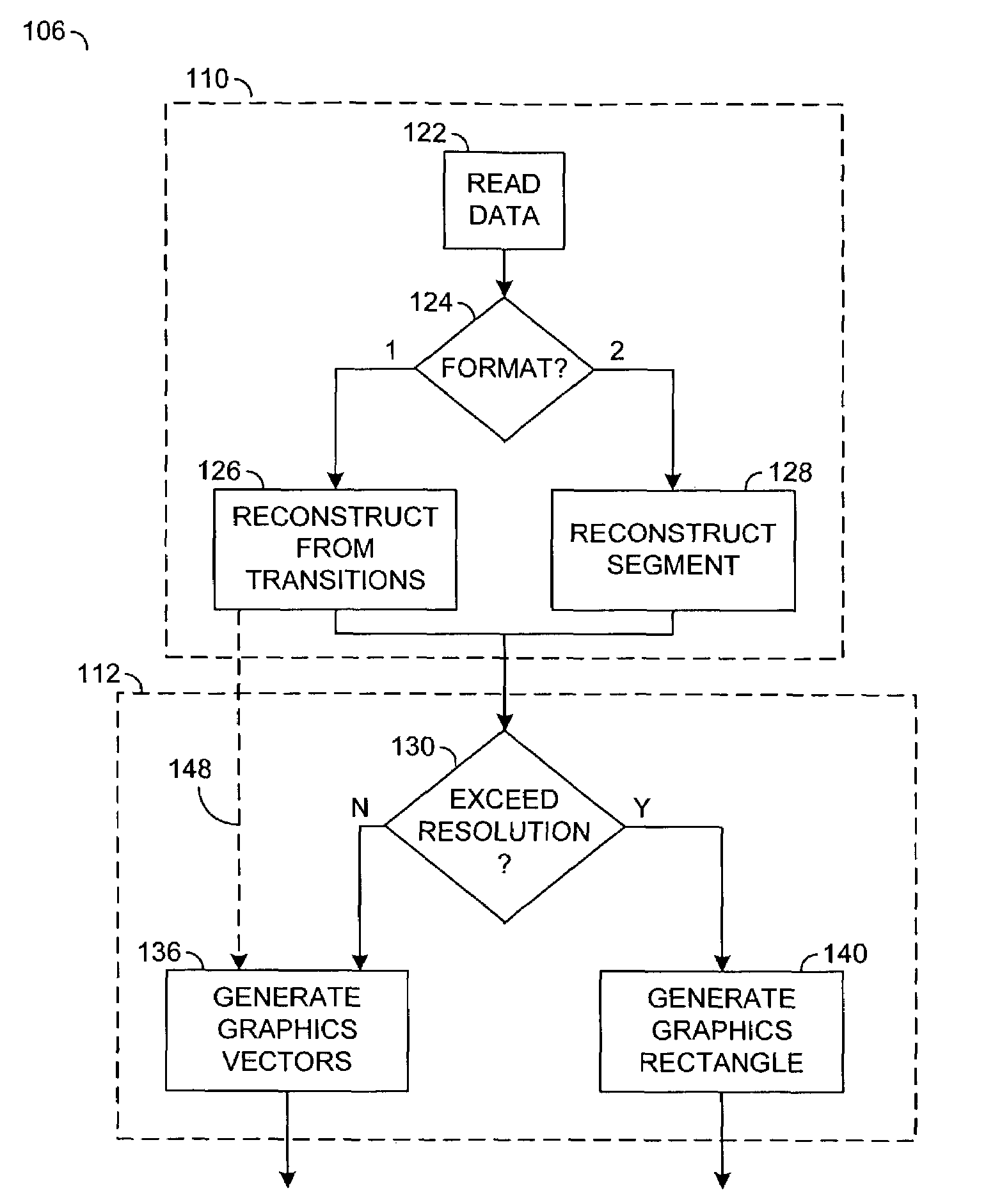
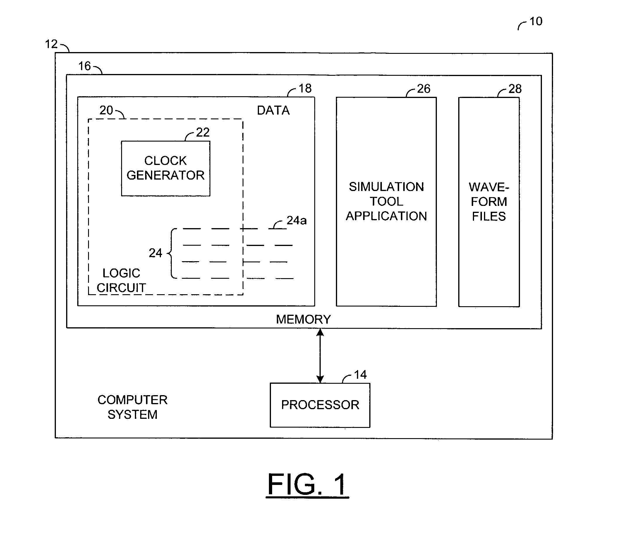
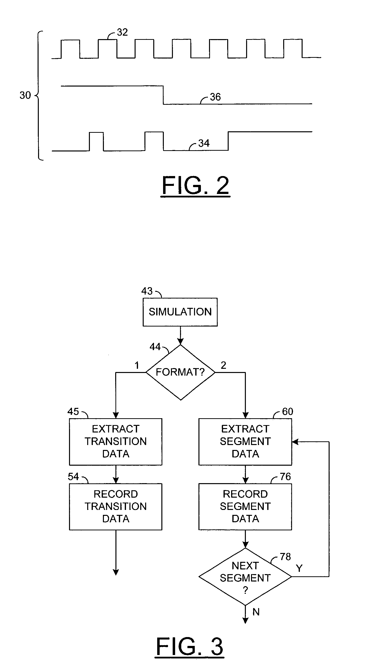
[0020]Referring to FIG. 1 a computerized simulation tool 10 may comprise a first computer system 12 including a processor 14 communicating with one or more regions of storage 16. The computer system 12 may comprise a workstation (not shown) coupled to a network (not shown). At least a portion of the storage 16 may be on the network (not shown). The storage 16 may include regions of one or more of magnetic media (e.g., a hard disc), optical media, and semiconductor media (e.g., memory circuitry). Stored in the storage 16 may be data 18 representing a model 20 of a logic circuit whose operation may be simulated. The logic circuit model 20 may include one or more clock signal generator blocks 22 for generating one or more clock signals for the logic circuit model 20. The logic circuit model 20 may include one of more interface nodes 24 for inputting and / or outputting signals to / from the logic circuit model 20. One or more of the nodes 24 may be a clock input node 24a for accepting a cl...


PUM


Abstract

A method for generating a compressed representation of a simulated waveform is disclosed. The method may have the steps of: (a) processing circuit model information, (b) identifying a segment of stable repetition; and (c) generating the compressed representation. Step (a) may generate waveform information representing a simulated waveform occurring in the circuit model. Step (b) may identify the segment in the waveform information. In step (c), the compressed waveform information may define the segment by (i) cycle information representing the waveform cycle and (ii) repetition information representing the stable repetitions of the waveform cycle to form the segment.

Description

FIELD OF THE INVENTION[0001]The present invention may relate to the field of simulation of electronic logic circuit behaviour, for example, for an integrated circuit. The invention may especially relate to recording and displaying logic signal waveforms generated by such a simulation.BACKGROUND OF THE INVENTION[0002]A simulation tool running on a computer is used to test a logic circuit design for an integrated circuit prior to manufacture of the integrated circuit. Logic signal waveforms generated in the simulation are recorded and later analysed by using a waveform display tool. A typical logic simulation of a circuit block of an Application Specific Integrated Circuit (ASIC) involves the use of one or more clocks running for an extended period of time. The clocks are normally of the order of tens to hundreds of Megahertz (MHz), and a simulation time is normally from several milliseconds to a second. Recording such high frequency signals results in a vast amount of recorded data. ...

Claims


Application Information

Patent Timeline
Patent Type & Authority Patents(United States)
IPC IPC(8): G06F17/50G01R13/02G06F17/00G06T11/00
CPCG06F17/5022G06T11/00G06F30/33
Inventor TESTER, DAVID
Owner BELL SEMICON LLC
Learn More