Wheel suspension arm

a technology for suspension arms and wheels, applied in resilient suspensions, interconnection systems, vehicle components, etc., can solve the problems of only applying after welding, rust prevention and painting, and relatively high cost of assembly/disassembly of trailing arms, etc., to achieve simple structure, low cost, and simple assembly.

Inactive Publication Date: 2011-03-08
SAF HOLLAND GMBH
View PDF22 Cites 21 Cited by
  • Summary
  • Abstract
  • Description
  • Claims
  • Application Information

AI Technical Summary

Benefits of technology

[0006]The present invention provides a wheel suspension arm for a vehicle, which can be fabricated cheaply and can be mounted / dismounted in simple fashion. Another aspect of the present invention is a corresponding method and a wheel suspension with such a wheel suspension arm.
[0008]Since the wheel suspension arm is simply clamped onto an axle tube, it can be easily mounted and dismounted. Furthermore, a wheel suspension with such a wheel suspension arm has a minimal number of structural parts. The axle tube and the wheel suspension arm can receive a rust preventative, a coat of paint or the like prior to the mounting, since welding is no longer necessary. Since the axle opening has essentially the same diameter as the corresponding segment of the axle element, a clamping is produced which can transmit a high torque. The axle opening preferably has a transition fit. However, it is also possible to provide a clearance fit with a slight play of around 0.05 mm to 0.5 mm, or a press fit, in which the axle opening has a slightly smaller diameter than the axle element. In this case, the trailing arm can be heated for installation, so as to widen the diameter, or the wheel suspension arm can be pressed onto the axle element. Furthermore, the peripheral edge of the axle opening can be spread open at the interruption, in order to widen the diameter.
[0012]The interruption may be formed by a slot, which ends in a recess formed in the wall region of the wheel suspension arm, such as in the form of a round or oval opening, or it is taken as far as the outer edge of the wheel suspension arm. In this way, the formation of stress cracks at one end of the interruption or slot is avoided.
[0013]Preferably the wheel suspension arm is cast from spherulitic graphite iron GGG, gray cast iron GG, or vermicular graphite cast iron GGV, so that is can be produced in economical manner.
[0015]Moreover, it is also preferable that at least one engaging means is arranged for a form-fitted engagement of the axle opening with an axle element, so that the axle element can be easily positioned in the trailing arm. Furthermore, the engaging means can form a fail-safe function in event of failure of the clamping and / or an indicator function to detect an undesirable twisting of the axle element.
[0016]The wheel suspension arm of the invention preferably has a T-profile or an essentially open double-T profile, so that the wheel suspension arm has high torsional and bending strength.

Problems solved by technology

Furthermore, any after treatment, such as rust prevention and painting, can only be applied after the welding.
But when using air springing, this type of fixation requires a plurality of individual parts and a relatively high cost of assembly / disassembly of the trailing arm, since each trailing arm is provided with additional positioning parts, and one has to tighten up four screws for each trailing arm.

Method used


Image

  • Wheel suspension arm
  • Wheel suspension arm
  • Wheel suspension arm

Examples


Embodiment Construction

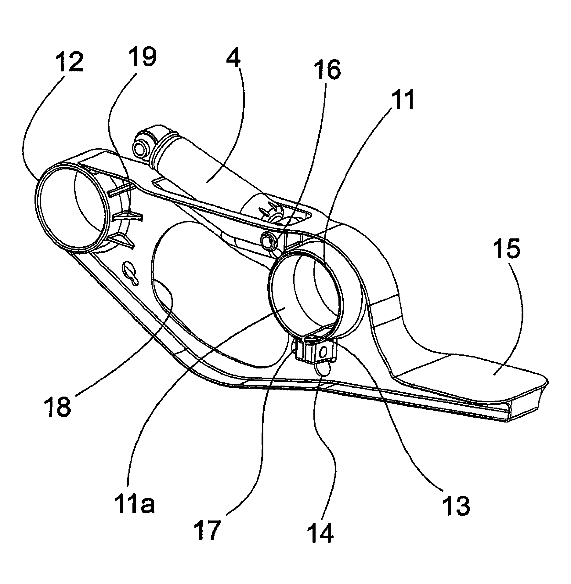
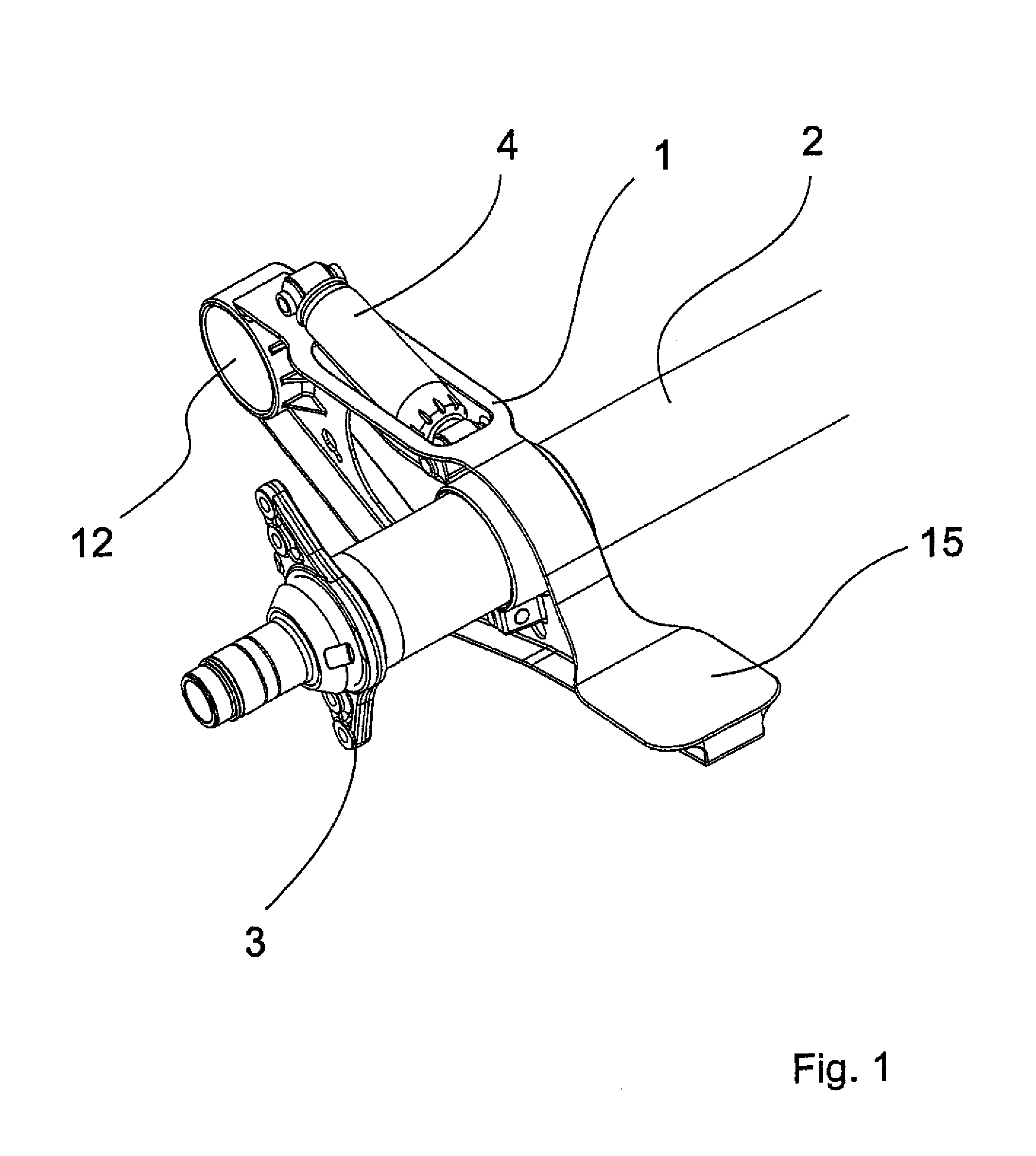
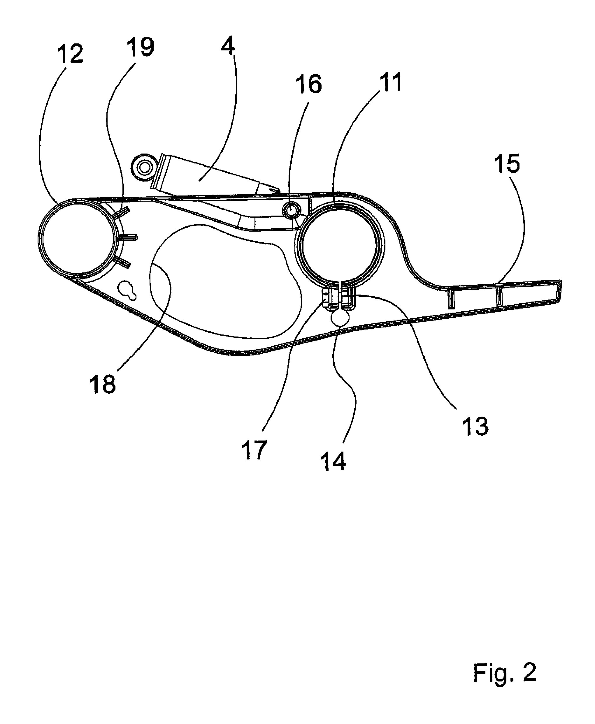
[0025]As is shown in FIG. 1, an axle tube 2 of a rigid axle extends through an axle opening 11 of a trailing arm 1 and a clamped brake holder 3 is arranged at one end of the axle tube 2. Furthermore, a shock absorber 4 is arranged on the trailing arm 1 and the trailing arm 1 has a spring receptacle 15 as well as a link opening 12. The trailing arm 1 is pivoted via the link opening 12 on a vehicle frame (not shown), for example, via a rubber-metal element. Furthermore, a spring element (not shown) is installed between a vehicle frame and the spring receptacle 15 of the trailing arm 1. The spring element preferably comprises an air spring (not shown). The axle tube 2 likewise has a trailing arm 1 on the other side of the vehicle (not shown), so that the wheel suspension is formed by a pair of trailing arms 1 and an axle tube 2.

[0026]The trailing arm 1 is preferably made from gray cast iron, such as GG-60, spherical graphite cast iron (spherulitic cast iron GGG) or vermicular graphitic...


PUM


Abstract

A wheel suspension arm comprises a link opening (12) for pivotably securing the wheel suspension arm to a vehicle frame and an axle opening (11) for securing an axle element (2) to the wheel suspension arm. A peripheral edge (11a) of the axle opening includes at least one discontinuation, such as a slot (13). A screw (17) can be tightened to clamp the axle element (2) in the axle opening (11). The invention also relates to a method for producing the inventive wheel suspension arm and to a wheel suspension comprising said wheel suspension arm.

Description

BACKGROUND OF THE INVENTION[0001](1) Field of the Invention[0002]The present invention concerns a wheel suspension arm, especially a trailing arm for a vehicle, as well as a wheel suspension with such a wheel suspension arm.[0003](2) Description of the Related Art[0004]In the prior art, according to utility model number DE 296 16 257 U1, a rigid axle consisting of an axle tube is led through a pair of boxlike trailing arms and welded to the trailing arms. In order to make possible a welding of the trailing arms to the axle tube, they must be fabricated of a material that lends itself to welding with the material of the axle tube, such as steel. Furthermore, any after treatment, such as rust prevention and painting, can only be applied after the welding.[0005]One can avoid a welding of the trailing arms to the rigid axle if the trailing arms are each clamped by a pair of U-shaped steel shackles to the rigid axle, as is shown in FIG. 4. This type of axle fixation is especially suitabl...

Claims


Application Information

Patent Timeline
Patent Type & Authority Patents(United States)
IPC IPC(8): B60G3/08
CPCB60G7/001B60G7/008B60G9/003B60G2204/129B60G2204/143B60G2206/014B60G2206/017B60G2206/16B60G2206/31B60G2206/601B60G2206/8101B60G2206/8201B60G2204/126
Inventor KOSCHINAT, HUBERT B.
Owner SAF HOLLAND GMBH
Why Eureka
Try Eureka