Bipolar pulse generators with voltage multiplication and pulse separation

a bipolar pulse generator and voltage multiplication technology, applied in pulse generators, pulse train generators, pulse techniques, etc., can solve the problems of high ratio impedance transformation, disadvantages of above-referenced bipolar pulse generators, and inability to provide voltage (impedance) transformation, etc., to achieve high pulse power, simple structure, and high voltage/impedance transformation

Inactive Publication Date: 2011-03-08
BAE SYST INFORMATION & ELECTRONICS SYST INTERGRATION INC
View PDF15 Cites 9 Cited by
  • Summary
  • Abstract
  • Description
  • Claims
  • Application Information

AI Technical Summary

Benefits of technology

[0010]The invention provides a bipolar pulse generator based on voltage charged transmission lines, which provides a separation between positive and negative sub-pulses. The bipolar pulse generator also produces high pulse power while providing high voltage / impedance transformation. In addition, the bipolar pulse generator of the invention can be implemented in a simple structure with a single switch, has a relatively small total size, and allows simple access by fibers to a photoconductive switch(s) that can be used to actuate the bipolar pulse generator.
[0017]In another embodiment of the present invention, the bipolar pulse generator may further include a charged stepped transmission line between the switch at its near end and the embedded transmission line segment at its distant end that facilitates voltage / impedance transformation. The impedance of the stepped transmission line may increase for each successive step. Moreover, the load and the second transmission line structure may have impedances that are higher than the maximum characteristic impedance of the stepped transmission line.

Problems solved by technology

The low range of characteristic impedances frequently causes problems for coupling with typically load impedances, for example 50 Ohm or higher, or radiating impedances, which introduces a problem with high ratio impedance transformation.
There are, however, disadvantages associated with the above-referenced bipolar pulse generators.
For example, all of the above-referenced generators do not provide voltage (impedance) transformation without an additional pulse transformer.
In addition, the conventional pulse generators are general complex in nature, require more than one switch, and can be difficult to implement in real world applications, especially for high power applications.
Still further, the switching elements required in U.S. Pat. No. 6,214,297 and SU Patent 1 254 994 A1 require very short (sub-nanosecond range) rise times, which are almost impossible to realize.
The lower characteristic impedance implies the lower space between line's conductors and the higher electric field, which is a limitation for selected voltage defined by switch.

Method used


Image

  • Bipolar pulse generators with voltage multiplication and pulse separation
  • Bipolar pulse generators with voltage multiplication and pulse separation
  • Bipolar pulse generators with voltage multiplication and pulse separation

Examples


Embodiment Construction

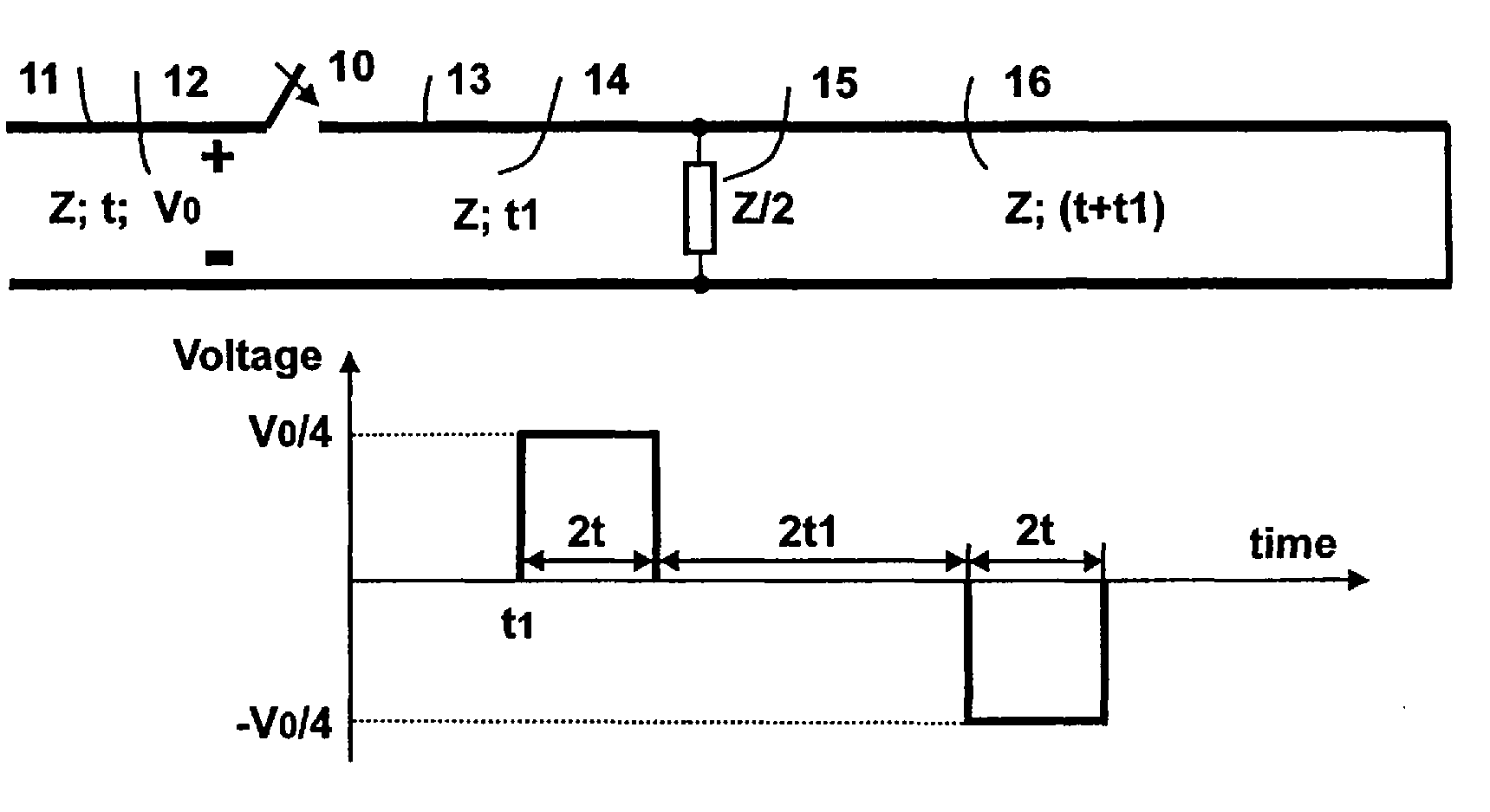
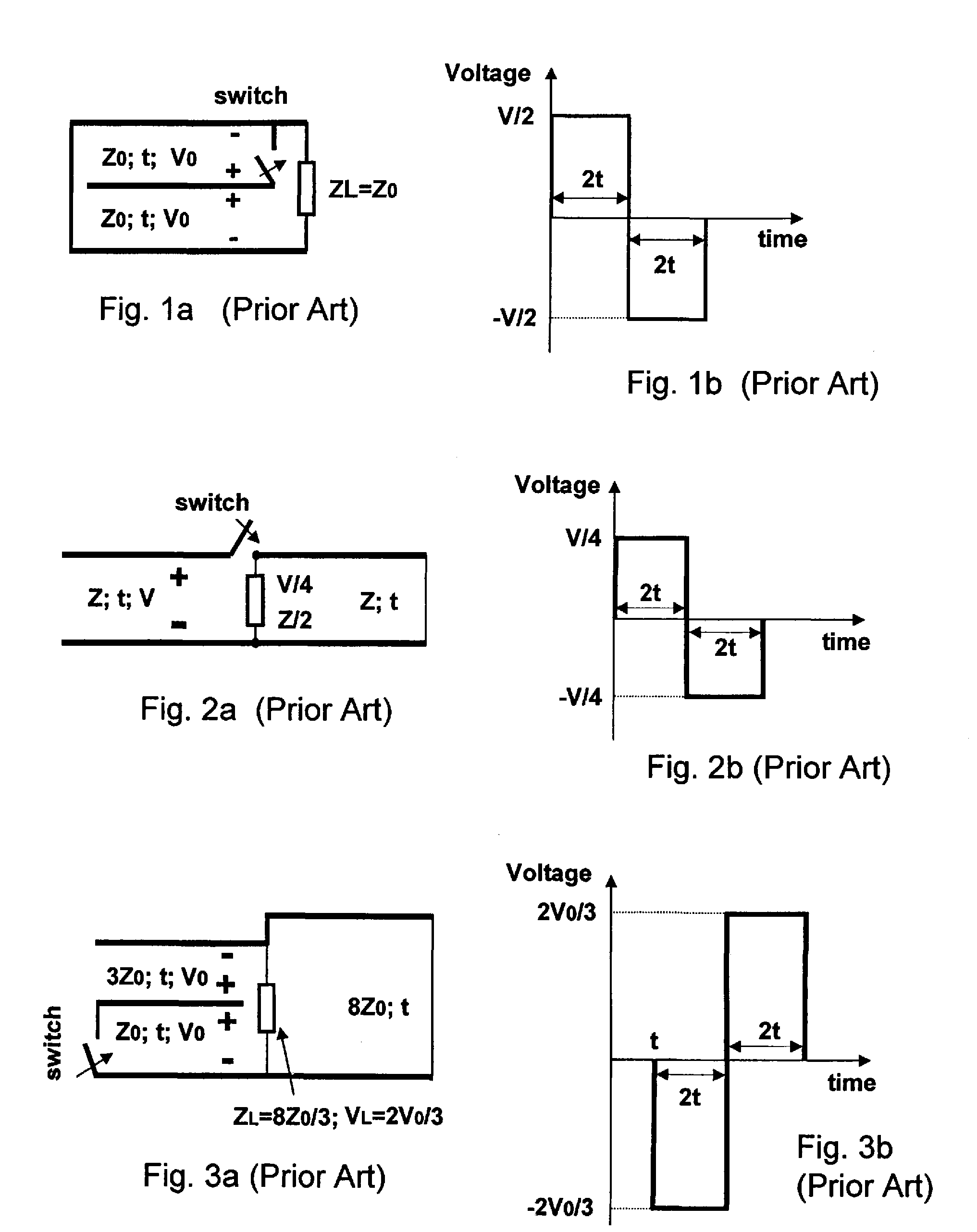
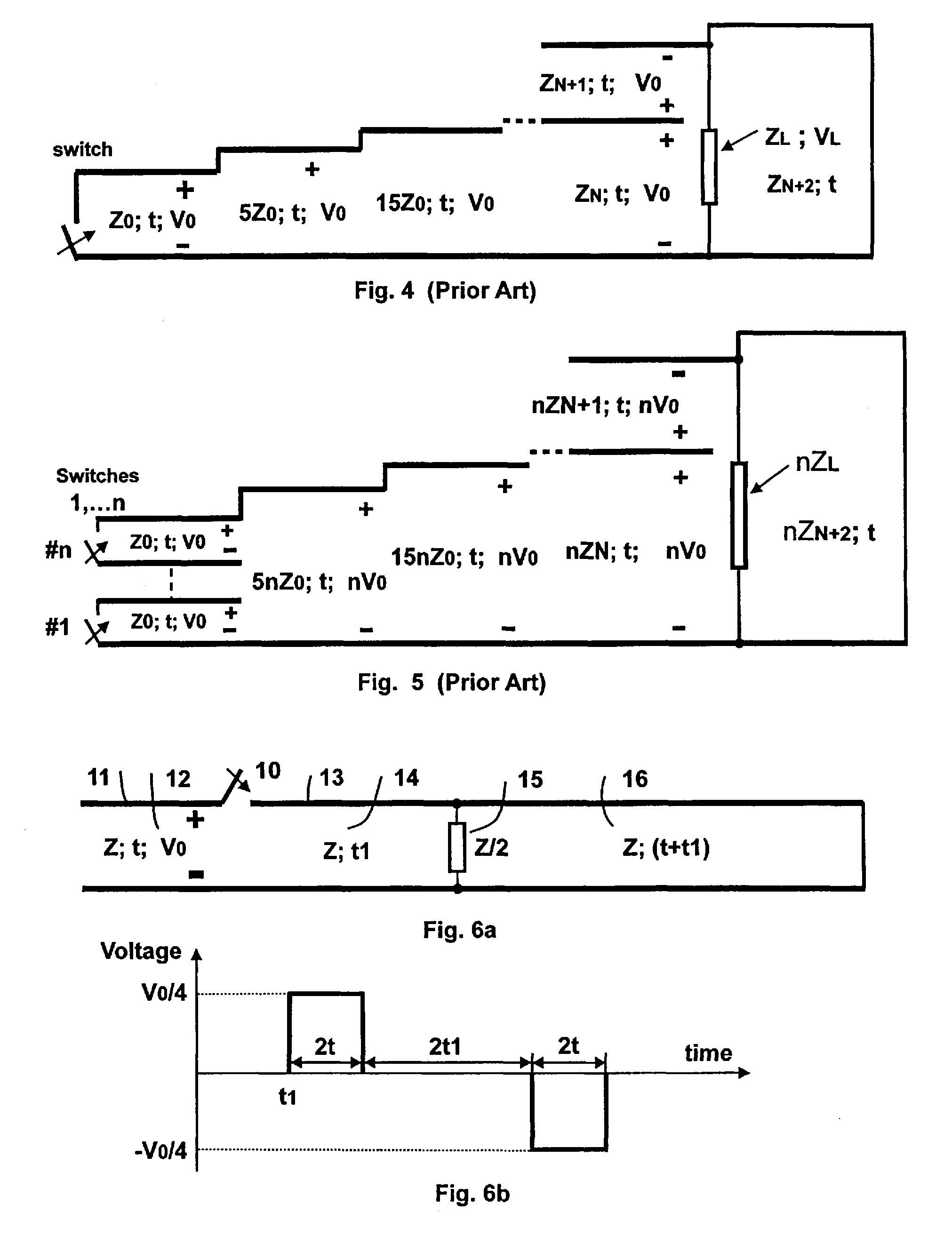
[0060]FIGS. 1-5 illustrated various-ratio impedance transformed bipolar pulse generators according to the prior art. FIG. 1a, for example, illustrates a bipolar pulse generator with a switch positioned inside a structure. FIG. 2a depicts a schematic diagram of a simple bipolar pulse generator with a switch that can be positioned outside a structure. FIG. 3a depicts a schematic of a single-stage bipolar pulse generator with increased impedance transformation. FIG. 4 depicts a schematic of an N-stage bipolar pulse generator according to the prior art with a charged stepped transmission line that provides high impedance and voltage transformation. FIG. 5 depicts a schematic of an N-stage bipolar pulse generator with a charged stepped transmission line in which first stage consists of n identical switched stacked transmission lines in a first stage that provides increased power / energy and impedance transformation by a factor n. The illustrated generators generate bipolar pulses without ...


PUM


Abstract

A bipolar pulse generator includes a pair of two-conductor transmission lines coupled together with a load positioned between the two transmission lines. Two segments of one transmission line are charged and switchably coupled to two segments of the other transmission line to produce a bipolar pulse on the matched load. The generator may include two transmission line structures coupled together with a load positioned between each transmission line structures. The first transmission line structure may include a stepped transmission line and an embedded transmission line segment. A switch is coupled between the embedded transmission line segment and another segment of the transmission line structure. During operation, the first transmission line structure is charged to a potential with the switch in the open position and, when the switch is closed, the charge on the first transmission line structure together with the second transmission line structure generates a bipolar pulse on the matched load.

Description

BACKGROUND[0001]The invention relates generally to bipolar pulse generators. More specifically, the invention relates to bipolar pulse generators that incorporate voltage multiplication (transformation) circuitry and time separation between positive and negative sub-pulses.[0002]Recent development trends in pulse power microwave sources for a variety of applications have been directed to increasing power and efficiency as well as energy density (energy per volume). Transmission line type pulse generators with different kinds of fast switches, including light activated photoconductive switches, can achieve some of the best results. In particular, such transmission line type pulse generators are compact and provide a very fast pulse rise time and a very high power.[0003]For a given limited charging voltage of transmission lines defined by high-current switches, high powered and high energy density transmission lines imply low characteristic impedances. The low range of characteristic ...

Claims


Application Information

Patent Timeline
Patent Type & Authority Patents(United States)
IPC IPC(8): H03K3/53H03K3/021
CPCH03K3/53
Inventor LONDON, SIMON
Owner BAE SYST INFORMATION & ELECTRONICS SYST INTERGRATION INC
Why Eureka
Try Eureka