Thermal processing furnace, gas delivery system therefor, and methods for delivering a process gas thereto

a technology of gas delivery system and thermal processing furnace, which is applied in the direction of lighting and heating apparatus, combustion types, and lump and pulverizing fuel, etc., can solve the problems of reduced quality and long-term reliability of dielectric layers of silicon dioxide grown by conventional wet or dry thermal oxidation processes, affecting the repeatability of processes, and reducing the thickness of the thickness

Inactive Publication Date: 2011-03-22
TOKYO ELECTRON LTD
View PDF22 Cites 243 Cited by
  • Summary
  • Abstract
  • Description
  • Claims
  • Application Information

AI Technical Summary

Problems solved by technology

Dielectric layers of silicon dioxide grown by conventional wet or dry thermal oxidation processes exhibit reduced quality and long-term reliability as the thickness is reduced.
After a thin layer of silicon oxynitride forms on the surface, the diffusion of oxidant species to the underlying silicon is greatly hampered.
When using nitrous oxide as a process gas for forming silicon oxynitride dielectrics, a problem that is encountered is process matching or the repeatability of a process among different tools when exactly the same process and hardware configuration is used.
Achieving process uniformity among the different thermal processing furnaces is desired but, unfortunately, rarely achieved.
Minor deviations from targeted manufacturing tolerances often result in a set of gas injectors that exhibits an asymmetrical or non-symmetric flow ratio among the individual gas injectors.
Attempts to manufacture different sets of gas injectors to identical dimensional tolerances so as to exhibit identical non-symmetric flow ratios as a master set of gas injectors is difficult, if not impossible.
Because of the inability to manufacture dimensionally matched sets of gas injectors, significant differences in the properties of the oxynitride layer may be apparent for the same intended process executing on different conventional thermal processing furnaces, which is unacceptable.

Method used


Image

  • Thermal processing furnace, gas delivery system therefor, and methods for delivering a process gas thereto
  • Thermal processing furnace, gas delivery system therefor, and methods for delivering a process gas thereto
  • Thermal processing furnace, gas delivery system therefor, and methods for delivering a process gas thereto

Examples


Embodiment Construction

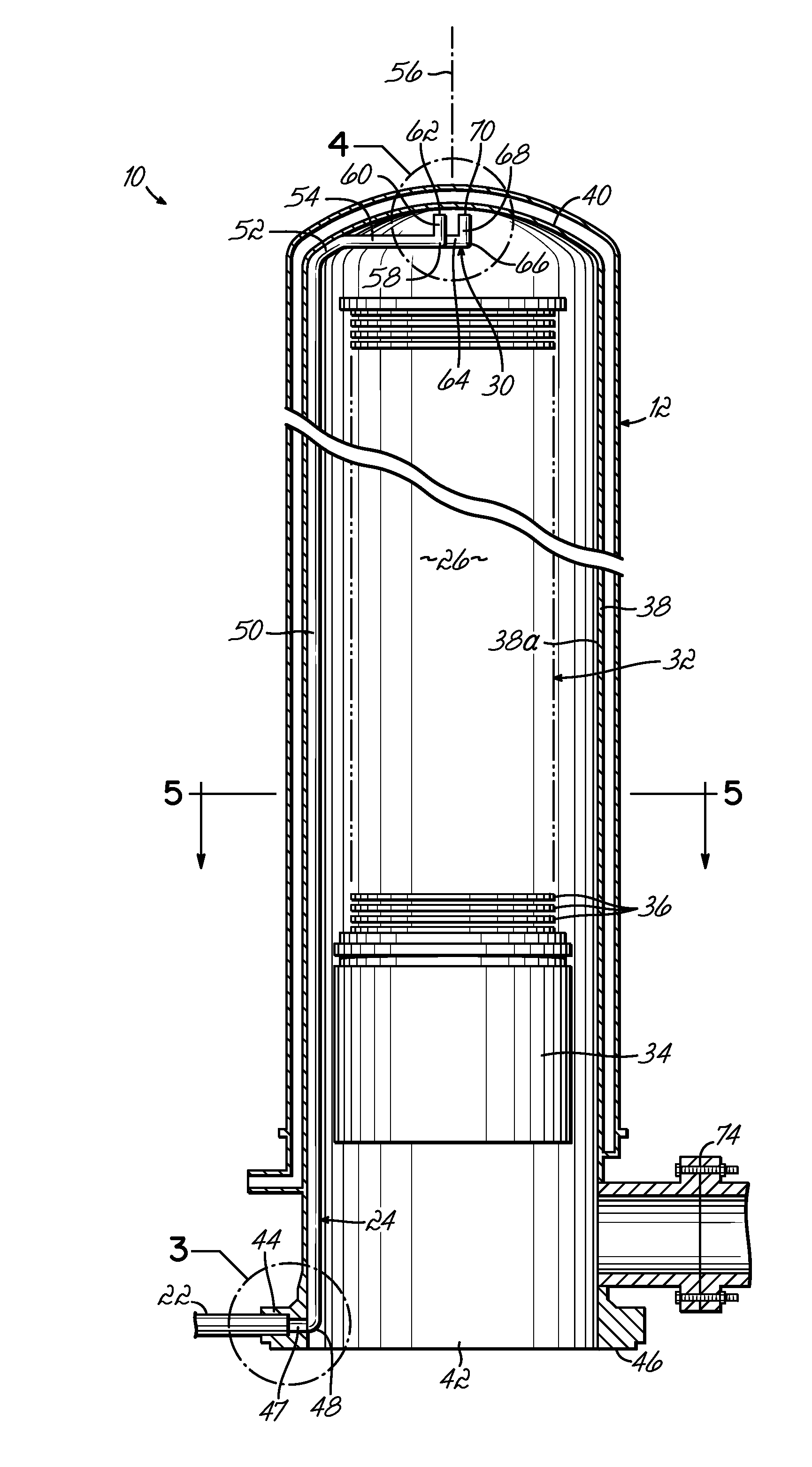
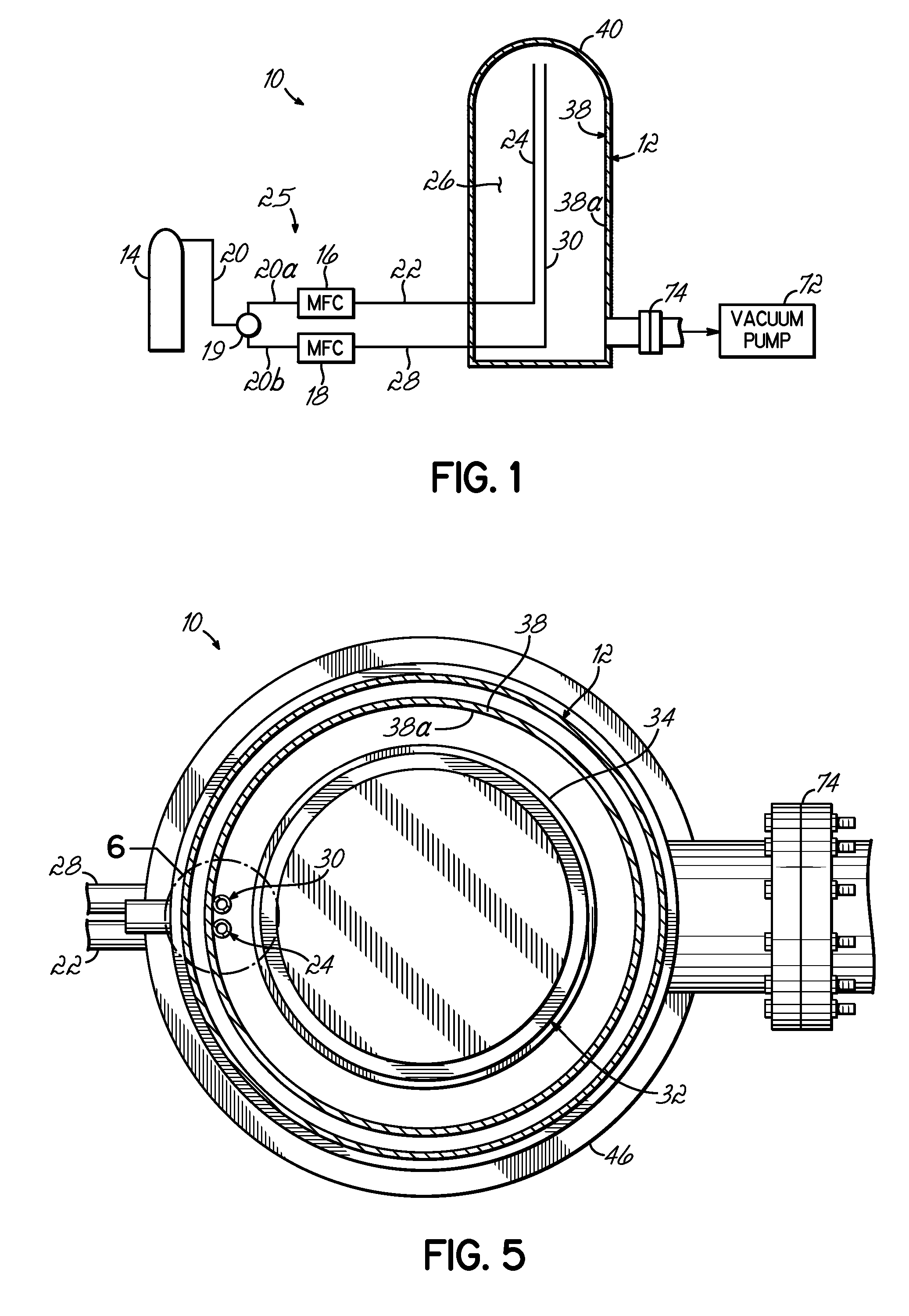
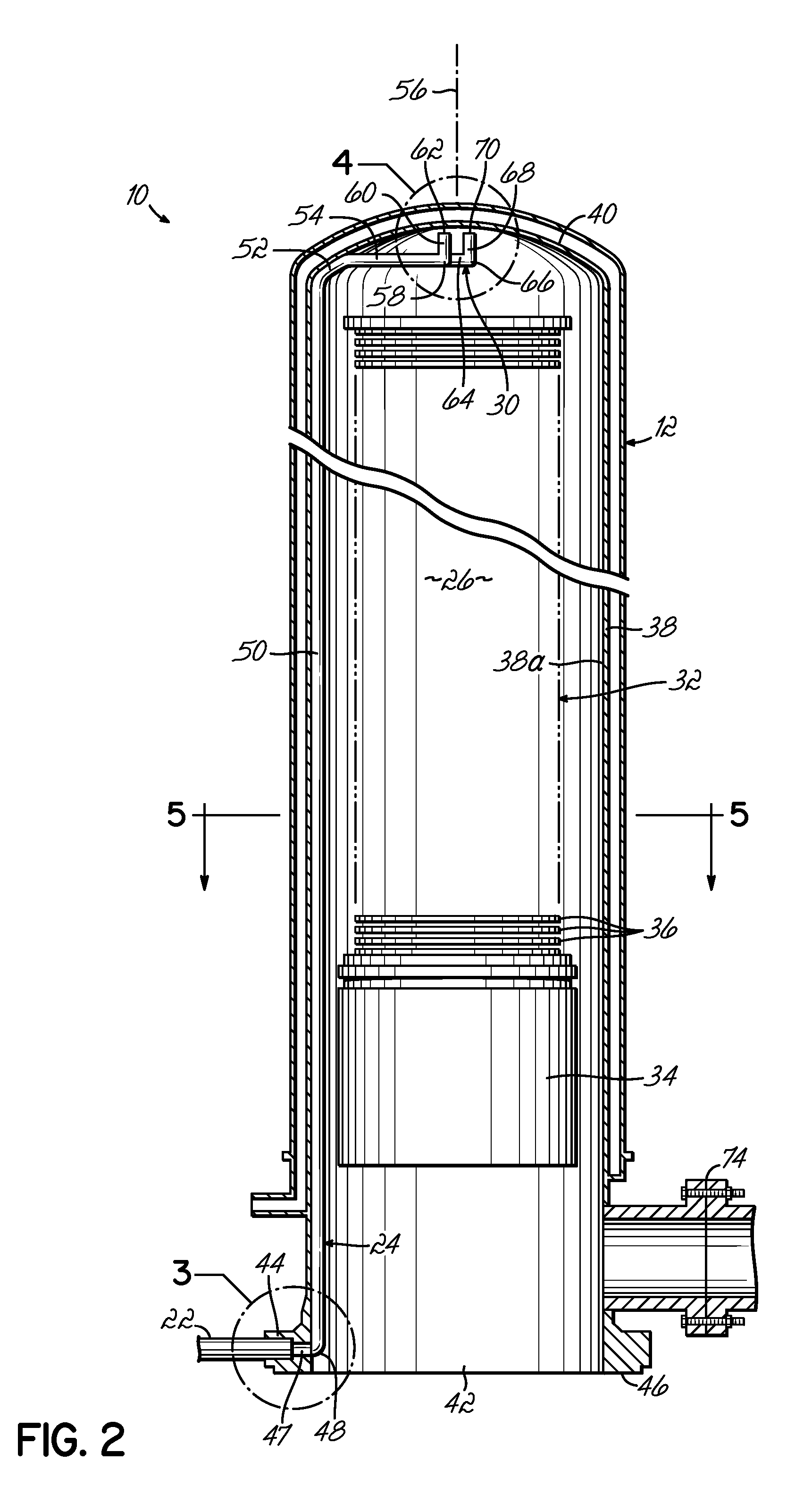
With reference to FIG. 1, a process tool in the form of a thermal processing furnace 10 comprises a furnace tube or outer housing 12 that surrounds a processing compartment or space 26 adapted to receive a batch of substrates 36 (FIG. 2). The thermal processing furnace 10 utilizes the process gas supplied from a gas supply 14, such as a gas cylinder of compressed process gas, for growing a layer on a batch of substrates 36 in the controlled atmosphere ambient of the processing space 26 that contains a partial pressure of a process gas. More specifically, the thermal processing furnace 10 may be used for thermal oxidation of silicon substrates 36 in a controlled atmosphere ambient containing a process gas such as, for example, nitrous oxide (N2O) to incorporate nitrogen atoms originating from the nitrous oxide into a silicon dioxide matrix to form a silicon oxynitride layer on a batch of semiconductor substrates 36. The invention contemplates that the process tool constituting the po...


PUM


Abstract

A gas delivery system for supplying a process gas from a gas supply to a thermal processing furnace, a thermal processing furnace equipped with the gas delivery system, and methods for delivering process gas to a thermal processing furnace. The gas delivery system comprises a plurality of regulators, such as mass flow controllers, in a process gas manifold coupling a gas supply with a thermal processing furnace. The regulators establish a corresponding plurality of flows of a process gas at a plurality of flow rates communicated by the process gas manifold to the thermal processing furnace. The gas delivery system may be a component of the thermal processing furnace that further includes a liner that surrounds a processing space inside the thermal processing furnace.

Description

FIELD OF THE INVENTIONThis invention relates to the field of semiconductor processing, and, more particularly, to gas delivery systems for a thermal processing furnace, thermal processing furnaces with a gas delivery system, and methods for delivering a process gas to a thermal processing furnace.BACKGROUND OF THE INVENTIONThermal processing furnaces are commonly used to perform a variety of semiconductor fabrication processes, including but not limited to oxidation, diffusion, annealing, and chemical vapor deposition (CVD). Most conventional thermal processing furnaces typically employ a processing chamber that is oriented either horizontally or vertically. Vertical thermal processing furnaces generate fewer particles during processing, which reduces substrate contamination, are readily automated, and require less floor space because of their relatively small footprint.One common application of thermal processing furnaces is the growth of high-quality thin dielectric layers during ...

Claims


Application Information

Patent Timeline
Patent Type & Authority Patents(United States)
IPC IPC(8): H01L21/31
CPCC30B25/14C30B31/16C30B35/00H01L21/3145H01L21/67109H01L21/28202H01L21/324Y10S438/935H01L21/0214H01L21/02249H01L21/02255
Inventor DIP, ANTHONYMALSTROM, ERIC J.
Owner TOKYO ELECTRON LTD
Why Eureka
Try Eureka