
Pulsed gliding arc electrical discharge reactors

a technology of electrical discharge reactor and gliding arc, which is applied in the direction of nitrogen oxide/oxyacid, chemical/physical/physical-chemical processes, nitric oxide, etc., can solve the problems of complex electrochemical processes, significant energy loss in both configurations, and the need for complex membrane and electrode systems

Active Publication Date: 2011-04-05
BURLICA RADU +1
View PDF4 Cites 14 Cited by
  • Summary
  • Abstract
  • Description
  • Claims
  • Application Information

AI Technical Summary

Benefits of technology

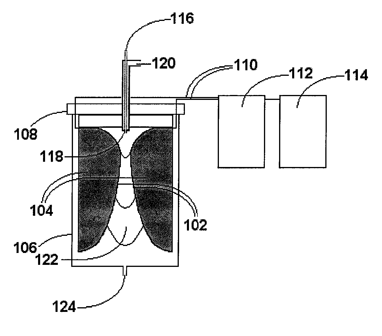
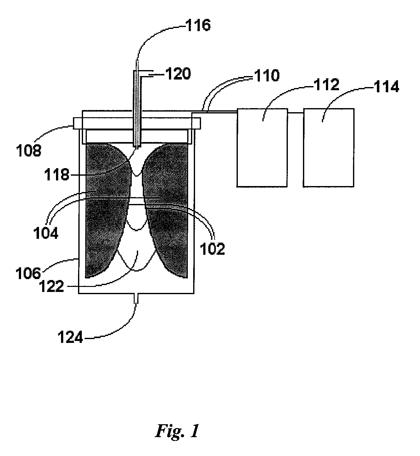
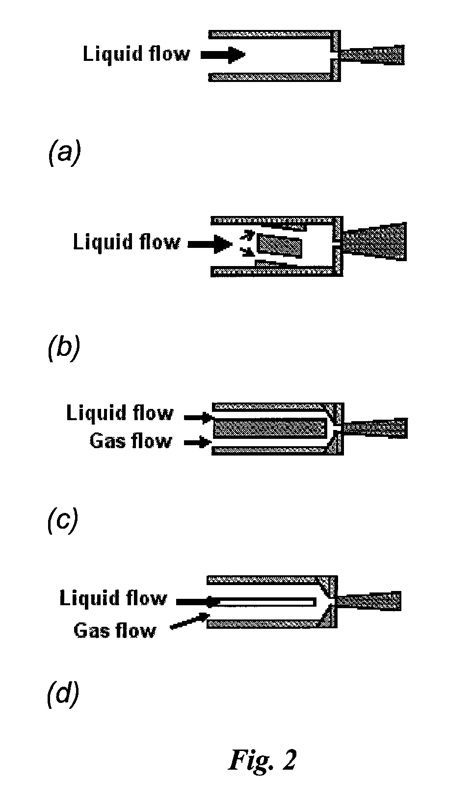
"The invention is a reactor that uses a pulsed plasma gliding arc discharge to chemically transform gas or gas and liquid mixtures. The reactor has a housing with at least one inlet to direct the gas or gas and liquid mixture to the plasma region, where it is generated between two or more divergent electrodes. The electrodes are connected to a pulsed power supply. The reactor housing is preferably electrically non-conductive. The gas-liquid inlet can be a two-way nozzle to maintain the plasma. The invention can be used to generate hydrogen peroxide or hydrogen from water, as well as degrade organic or inorganic pollutants in water. The technical effects of the invention include improved chemical transformation efficiency and reduced pollutant levels in water."

Problems solved by technology

Both configurations have significant energy losses by thermal effect.
Those electrochemical processes require more complicated membrane and electrode systems than does gliding arc technology.

Method used


Image

  • Pulsed gliding arc electrical discharge reactors
  • Pulsed gliding arc electrical discharge reactors
  • Pulsed gliding arc electrical discharge reactors

Examples


example 1

Water was passed separately through the ACG reactor and the PGD reactor. The water displayed an initial pH of 5 and a conductivity of 10 μS / cm. The working gas was varied using individually air, nitrogen, oxygen and argon for each reactor. A quantity of 200 mL of water was used for each reactor and multiple passes were made for each 200 mL quantity through each reactor. Measurements of the solution parameters were carried out on the water after each pass.

For both reactors the evolution of the pH was similar. Using the ACG reactor the pH decreased from the initial value of 5 to a value of approximately 2.5 after four passes. Using the PGD reactor, the pH decreased from the initial value of 5 to a value of approximately 3 after four passes. The change in pH did not differ in a significant manner using different working gases.

The change in conductivity is shown in FIG. 4. The change in conductivity differed significantly with the two reactors. In the case of the ACG reactor, shown in F...

example 2

The treatment of aqueous solutions of the pentasodium salt of the dye blue 137,

was examined, separately using the ACG reactor and the PGD reactor. The working gas was varied using individually air, nitrogen, oxygen and argon for each reactor. A quantity of 200 mL of a 20 mg / L aqueous blue dye solution was passed multiple times through each reactor. Absorbance measurements of the dye were performed by UV spectroscopy using a Perkin-Elmer / Lambda 3A spectrometer after each pass and the measured absorbance was used to calculate a concentration by mass of the dye. The results of the blue dye degradation are presented in FIG. 7(a) for the ACG reactor and in FIG. 7(b) for the PGD reactor. As can be seen in FIG. 7(a), the degradation of the dye with the first pass was rapid, with at least fifty percent degradation on the first pass for all working gases, but highly dependent on the working gas composition. The degradation was most rapid in air and least rapid in argon. By the second pass li...


PUM


Abstract

A pulsed gliding arc discharge (PGD) reactor includes an ignition coil driven by a pulse generator which is connected to a pair of divergent electrodes fixed by a reactor housing with a fluid inlet and outlet. Hydrogen peroxide and dye degradation can be carried out with a PGD reactor according to the invention with efficiencies that are more than two orders of magnitude greater than a conventional ACG reactor based on the calculated specific energy yield.

Description

STATEMENT REGARDING FEDERALLY SPONSORED RESEARCH OR DEVELOPMENTNot applicable.FIELD OF THE INVENTIONA pulsed gliding arc electrical discharge reactor that is useful for chemical transformations in liquids and gases.BACKGROUND OF THE INVENTIONIn order to degrade organic pollutants in aqueous solutions a number of advanced oxidation methods such as direct Fenton's reactions, electrochemical methods, DC corona discharge, pulse corona discharge, photocatalysis, and UV photolysis have been applied. Gliding arc or glidarc technology has been demonstrated to be effective at removing organic compounds from aqueous solutions and gases. A gliding arc is an electrical discharge formed between two or more thin “knife-edge” divergent electrodes with a high velocity (>1 m / s) gas flowing between the electrodes to prevent sparking. The electrical discharge is formed in the gas phase between two or three divergent electrodes at the smallest gap between the electrodes and the discharge spreads as ...

Claims


Application Information

Patent Timeline
Patent Type & Authority Patents(United States)
IPC IPC(8): B01J19/08
CPCB01J19/088C02F1/4608C02F2101/30B01J2219/0004B01J2219/0809B01J2219/0815B01J2219/0828B01J2219/0835B01J2219/0841B01J2219/0849B01J2219/0869B01J2219/0877B01J2219/0884B01J2219/0894C02F1/722B01J2219/00038
Inventor BURLICA, RADULOCKE, BRUCE R.
Owner BURLICA RADU
Learn More