Thermally enhanced magnetic transformer

a technology of magnetic transformers and heat sinks, applied in the field of planar transformers, can solve the problems of insufficient thermal performance of mounted heat sinks, limited minimum size of power supplies such as electronic systems, and inability to meet the requirements of power supply requirements, etc., and achieve the effect of thermally efficien

Active Publication Date: 2011-04-05
FLEXTRONICS AP LLC
View PDF58 Cites 21 Cited by
  • Summary
  • Abstract
  • Description
  • Claims
  • Application Information

AI Technical Summary

Benefits of technology

[0009]In one aspect of the invention, a planar transformer comprises a laminate substrate having an opening. Metal traces are wound about the opening to form a primary and a secondary winding. A core is configured to fit inside the opening and around the windings. At least one heat sink fin is integrally formed with the core. Because the core and heat sink are integrally formed, there is no additional step to mount the heat sink. Moreover, this eliminates the use of a thermal interface between the core and the heat sink making the assembly thermally more efficient than a system that has a heat sink mounted to the core. In some embodiments, the core comprises a ferrite ceramic. Alternatively, the core is iron or an iron alloy.
[0010]The central core is configured to pass through an aperture formed in a central position of the laminate substrate internal to the primary winding and the secondary winding. In some embodiments, the central core is integrally formed with a top core, and at least partially surrounds the primary winding and the secondary winding. Alternatively, a bottom core is configured to mount to the central core and the top core such that the core that comprises a central core, top core and bottom core substantially surrounds the primary winding and the secondary winding in the usual manner. In some embodiments, the bottom core couples with the top core and the central core to form an air gap for enhanced magnetic properties. When at least partially exposed to ambient air, the heat sink fins transfer heat from the planar transformer to the ambient air by convection.

Problems solved by technology

Power supplies have a limited minimum size that such electronic systems can attain, relying as they do on relatively large transformers with relatively large ferrite cores and magnet wire windings.
However, given the compact size and planar configuration, planar transformers are often tightly packed into an area and come into thermal contact with other circuits, and the like.
Simply mounting a heat sink element to a planar transformer may not be satisfactory.
The thermal performance of a mounted heat sink can be inadequate.
Furthermore, the addition of a heat sink increases the number of steps to manufacture a system that has a planar transformer and will increase the cost of manufacturing such a device.

Method used


Image

  • Thermally enhanced magnetic transformer
  • Thermally enhanced magnetic transformer
  • Thermally enhanced magnetic transformer

Examples


Embodiment Construction

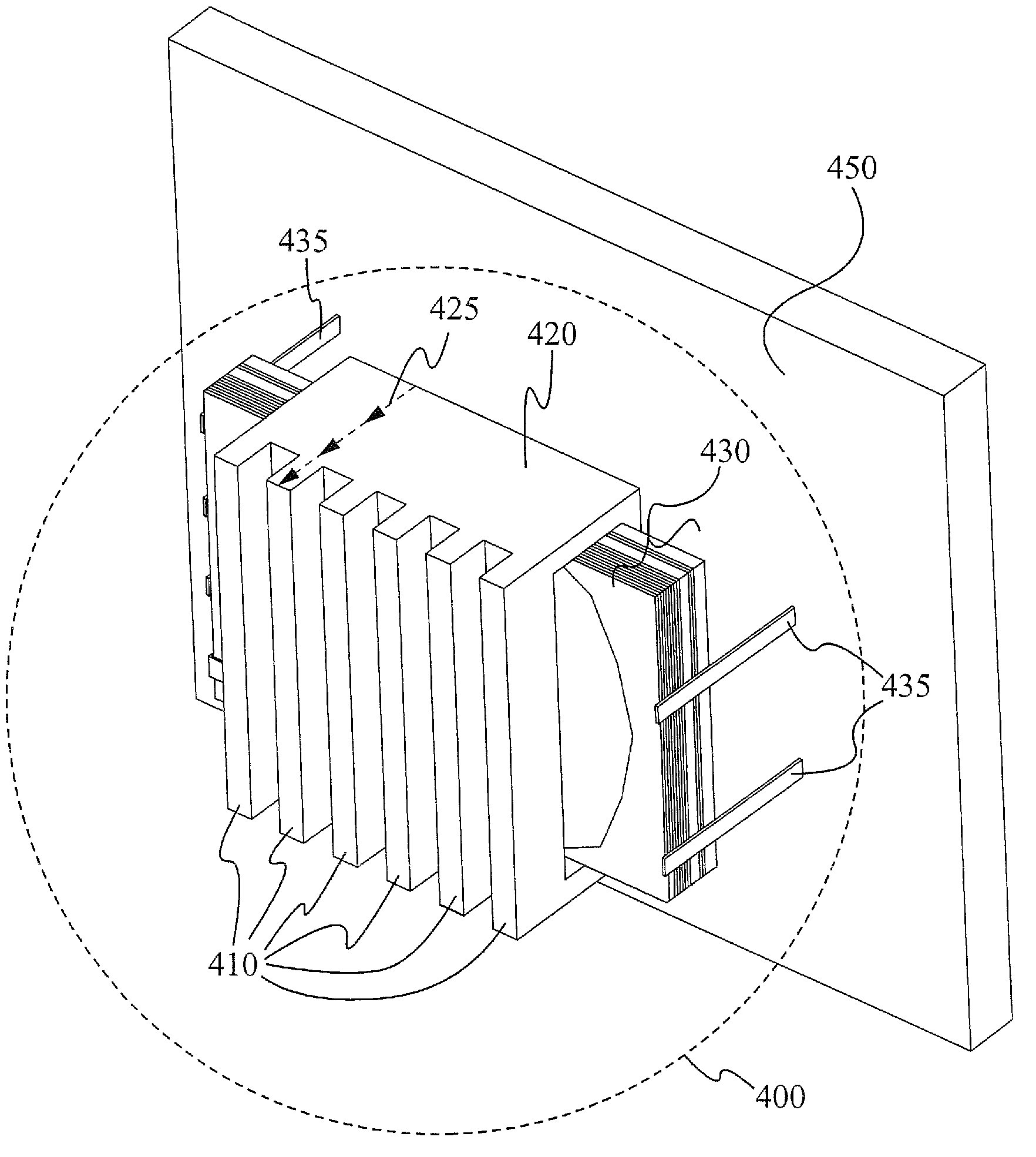
[0022]An improved apparatus and improved techniques are shown relating to a planar transformer having enhanced thermal performance. Those of ordinary skill in the art will realize that the following detailed description of the present invention is illustrative only and is not intended to limit the claimed invention. Other embodiments of the present invention will readily suggest themselves to such skilled persons having the benefit of this disclosure. It will be appreciated that in the development of any such actual implementation, numerous implementation-specific decisions can be made to achieve specific goals. Reference will now be made in detail to implementations of the present invention as illustrated in the accompanying drawings. The same reference indicators will be used throughout the drawings and the following detailed description to refer to the same or like parts.

[0023]Although transformers are generally efficient devices, they still generate some heat. The present invent...


PUM

PropertyMeasurementUnit
heat conductionaaaaaaaaaa
thermal conductivityaaaaaaaaaa
sizeaaaaaaaaaa

Abstract

A planar transformer comprises a laminate substrate having an opening with metal traces wound thereabout forming a primary and a secondary winding, a core configured to fit inside the opening to enclose the laminate substrate. At least one heat sink fin is integrally formed with the top, bottom or both sides of the core. A method of forming a planar transformer comprises laminating a substrate having an opening with metal traces wound thereabout forming a primary and a secondary winding, fitting a core inside the opening, and enclosing the laminate substrate. One of the top, bottom or both sides of the core include one or more heat sink fins.

Description

RELATED APPLICATIONS[0001]This Patent Application claims priority under 35 U.S.C. §119 (e) of the U.S. Provisional Patent Application Ser. No. 60 / 995,328, filed Sep. 25, 2007, and entitled, “THERMALLY ENHANCED PLANAR MAGNETIC TRANSFORMER,” which is also hereby incorporated by reference in its entirety.FIELD OF THE INVENTION[0002]The present invention relates generally to the field of planar transformers. More specifically, the present invention relates to thermal management for planar transformers.BACKGROUND OF THE INVENTION[0003]Power supplies have a limited minimum size that such electronic systems can attain, relying as they do on relatively large transformers with relatively large ferrite cores and magnet wire windings. Planar transformers ease this limitation and allow designers to achieve the low profiles required for circuit board mounting in space constrained applications. Connections to an outside circuit, such as the power semiconductors, are made by standard circuit board...

Claims


Application Information

Patent Timeline
Patent Type & Authority Patents(United States)
IPC IPC(8): H01F27/08H01F5/00H01F27/28
CPCH01F27/22H01F41/0206Y10T29/49073H01F2027/297H01F2027/2819
Inventor SHABANY, YOUNESAGUAYO, JUANRAO, SRINIVAS
Owner FLEXTRONICS AP LLC
Why Eureka
Try Eureka