Anti-scatter grid and collimator designs, and their motion, fabrication and assembly

a collimator and anti-scatter technology, applied in the field of focused and unfocused grids and collimators, can solve the problems of grid pattern and associated motion, requiring an increase in x-ray dose, and difficult interpretation, so as to reduce scattering of radiation, eliminate undesirable radiation detection, and improve image resolution

a collimator and anti-scatter technology, applied in the field of focused and unfocused grids and collimators, can solve the problems of grid pattern and associated motion, requiring an increase in x-ray dose, and difficult interpretation, so as to reduce scattering of radiation, eliminate undesirable radiation detection, and improve image resolution

US7922923B2Active Publication Date: 2011-04-12CREATV MICROTECH

Image

  • Anti-scatter grid and collimator designs, and their motion, fabrication and assembly
  • Anti-scatter grid and collimator designs, and their motion, fabrication and assembly
  • Anti-scatter grid and collimator designs, and their motion, fabrication and assembly

Examples


Embodiment Construction

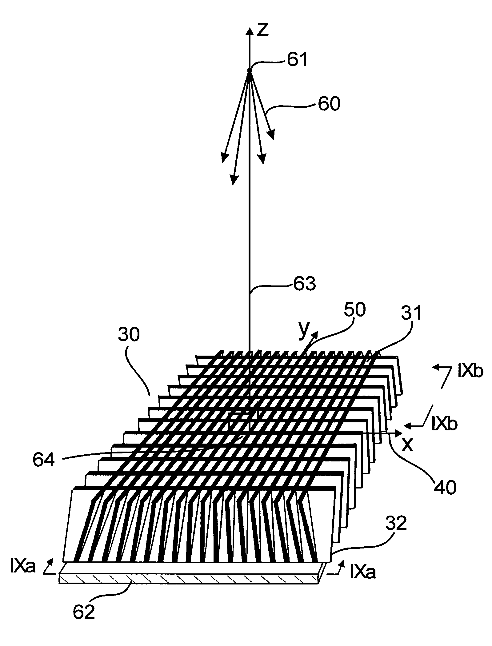
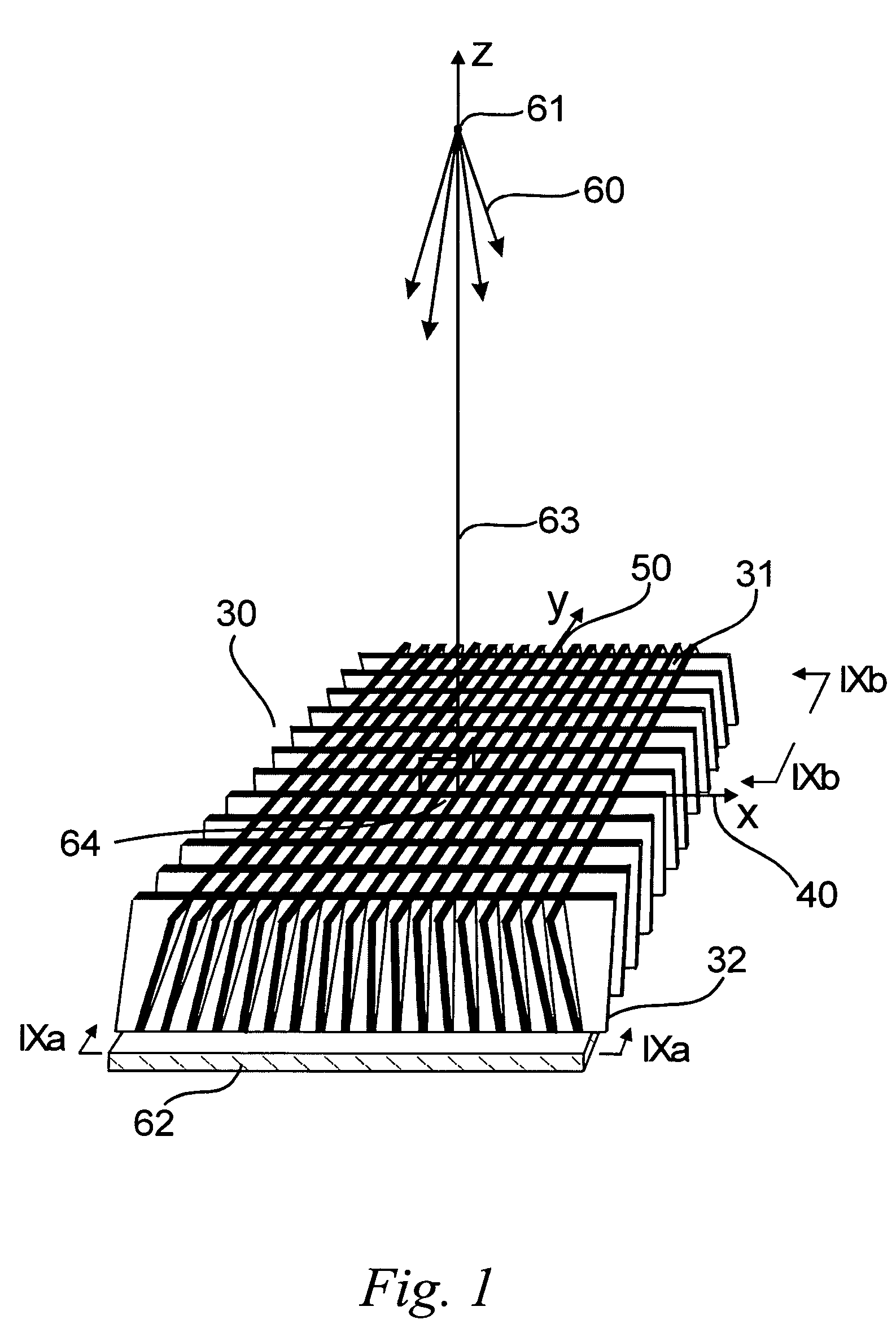
[0096]The present invention provides designs, methods and apparatuses for making large area, two-dimensional, high aspect ratio, grids, collimators, grid / scintillators, collimator / scintillators, x-ray filters and other such devices, with focused walls, defocused walls, variable focus walls, parallel walls and other such orientations, as well as similar designs, methods and apparatuses for all electromagnetic radiation applications. Referring now to the drawings, FIG. 1 shows a schematic of a section of an example of a two-dimensional grid or collimator 30 produced in accordance with an embodiment of a method of the present invention. The method of grid manufacture described here is different from the embodiment of the invention, as described in more detail in U.S. Pat. Nos. 5,949,850 and 6,252,938 referenced above, the entire contents of both being incorporated herein by reference

A. X-Ray Imaging

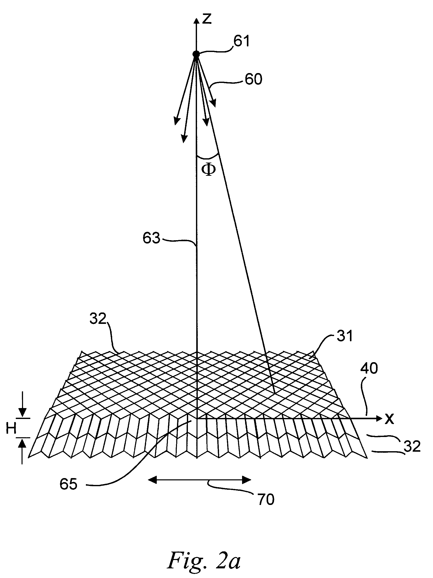
[0097]In FIG. 1, the x-ray propagates out of a point source 61 with a conical spread 60....


PUM

PropertyMeasurementUnit
energyaaaaaaaaaa
heightaaaaaaaaaa
aspect ratioaaaaaaaaaa

Abstract

Grids and collimators, for use with electromagnetic energy emitting devices, include at least a metal layer that is formed, for example, by electroplating / electroforming or casting. The metal layer includes top and bottom surfaces, and a plurality of solid integrated walls. Each of the solid integrated walls extends from the top to bottom surface and has a plurality of side surfaces. The side surfaces of the solid integrated walls are arranged to define a plurality of openings extending entirely through the layer. At least some of the walls also can include projections extending into the respective openings formed by the walls. The projections can be of various shapes and sizes, and are arranged so that a total amount of wall material intersected by a line propagating in a direction along an edge of the grid is substantially the same as another total amount of wall material intersected by another line propagating in another direction substantially parallel to the edge of the grid at any distance from the edge. Methods to fabricate these grids using copper, lead, nickel, gold, any other electroplating / electroforming materials, metal composites or low melting temperature metals are described.

Description

[0001]This application is a continuation in part of U.S. patent application Ser. No. 11 / 188,210 filed Jul. 25, 2005 now U.S. Pat. No. 7,310,411 which is a continuation of U.S. patent application Ser. No. 10 / 060,399 filed Feb. 1, 2002 now U.S. Pat. No. 6,987,836, which_claims benefit under 35 U.S.C. §119(e) from U.S. Provisional Patent Application Ser. Nos. 60 / 265,353 and 60 / 265,354, both filed on Feb. 1, 2001, the entire contents of all of these documents being incorporated herein by reference.CROSS-REFERENCE TO RELATED APPLICATIONS AND PATENT[0002]Related subject matter is disclosed in U.S. patent application Ser. No. 09 / 459,597, filed on Dec. 13, 1999, in U.S. patent application Ser. No. 09 / 734,761, filed Dec. 13, 2000, and in U.S. Pat. No. 5,949,850, the entire contents of all of these documents are expressly incorporated herein by reference.BACKGROUND OF THE INVENTION[0003]1. Field of the Invention[0004]The present invention relates to a method and apparatus for making focused a...

Claims


Application Information

Patent Timeline
12 Apr 2011
Publication
US7922923B2
IPC
B44C1/22; C03C15/00; C03C25/68
CPC
G21K1/025
Inventors
TANG, CHA-MEI; MAKAROVA, OLGA V.