Neutron detector
a neutron detector and neutron beam technology, applied in the field of neutron detectors, can solve the problems of limiting the usefulness of many applications, the size of the micro bubble was too small to capture all the energy, and the composition of the glass micro bubble was generally unsuitable for containing, so as to reduce voltage and power requirements, reduce the effect of neutron detection, and improve the signal characteristics
- Summary
- Abstract
- Description
- Claims
- Application Information
AI Technical Summary
Benefits of technology
Problems solved by technology
Method used
Image
Examples
example 1
[0052]Theoretical results for one dielectric sensor detector balloon: Tables 1 and 2 below are derived from the results of theoretical calculations of wall effects (edge effects) for neutron reaction products and electrons from gammas. The tables define both the preferred range of parameters estimated to provide optimal performance and the range of parameters estimated to provide useful but non-optimal performance. As these values were derived from theoretical calculations, some lie beyond what is currently practical, given the existing state-of-the-art in materials science. For example, the current upper limit for gas pressure in small sensors is around 103 atmospheres, while for very small sensor sizes (e.g. 10−3 cm) the theoretical maximum pressure is much higher.
[0053]
TABLE 1Suitable sensor sizes (interior diameter of a sphericaldielectric sensor balloon) as a function of gas density.Gas DensityMinimumPreferredPreferredMaximum(g / cc)Size (cm)Min (cm)Max (cm)Size (cm)1.00E−051.19E...
example 2
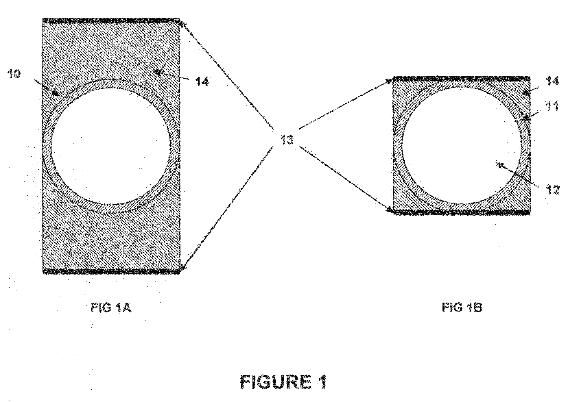
[0056]Applicants constructed a number of dielectric sensors consisting of gas-filled spherical balloons 10 (i.e. having an outer shell 11 and a hollow interior 12 filled with gas). Based on the foregoing calculations, the sensors had an outer diameter of 7 mm with 200 μm thick glass walls 11. (Although the sensors were made of glass, it will be appreciated that sensors can be made from a number of other ceramic or dielectric materials, provided they have the necessary electrical and mechanical characteristics.) The interior 12 of each sensor was filled with a gas mixture consisting of 3 atm 3He and 5 atm Ar. This combination of gas composition, gas pressure, and sensor size was sufficient for most 3He neutron capture events to deposit much or all of the energy released from the neutron capture reaction (in the form of energetic reaction products) in the sensor gas. Simultaneously, the combination of sensor size and gas pressure / density was low enough such that most gamma-induced ele...
example 3
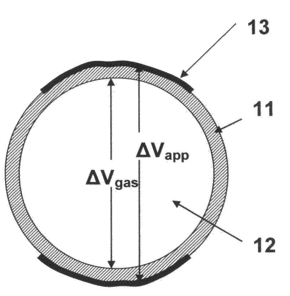
[0074]Assuming a spherical dielectric sensor filled with gas, the fraction of the voltage drop across the gas may be estimated by approximating the electrodes and sensor walls as parallel plates, using the formula:
ΔVgas / ΔVapp=t / [(2tw / k)+t], [Equation 1]
where ΔVapp is the applied voltage across the electrodes, ΔVgas is the drop in voltage across the sensor gas, k is the dielectric constant of the glass, tw is the wall thickness, and t is the inner circumference of the sensor. These parameters are depicted in FIG. 3. Sensor size and wall thickness may vary, but it can be seen in Equation 1 above that it is the ratio of these values, rather than their absolute values, that matters. Glass dielectric constant can also vary. FIG. 4 shows the fraction of the voltage drop occurring within the sensor gas as a function of glass dielectric constant for different total wall thickness to total sensor size ratios varying from 0.02 to 0.10. The plots cover various preferred ranges of size and wal...
PUM
| Property | Measurement | Unit |
|---|---|---|
| thickness | aaaaa | aaaaa |
| thickness | aaaaa | aaaaa |
| diameter | aaaaa | aaaaa |
Abstract
Description
Claims
Application Information
 - R&D
- Intellectual Property
- Life Sciences
- Materials
- Tech Scout
- Unparalleled Data Quality
- Higher Quality Content
- 60% Fewer Hallucinations
Browse by: Latest US Patents, China's latest patents, Technical Efficacy Thesaurus, Application Domain, Technology Topic, Popular Technical Reports.
© 2025 PatSnap. All rights reserved.Legal|Privacy policy|Modern Slavery Act Transparency Statement|Sitemap|About US| Contact US: help@patsnap.com


