Exhaust gas recirculation system for internal combustion engine

a technology of exhaust gas recirculation and internal combustion engine, which is applied in the direction of machines/engines, mechanical equipment, and non-fuel substance addition to fuel, etc., can solve the problems of foreign particles easily trapped in the trapping device, and achieve the effect of reducing the flow speed of egr gas and reducing foreign particles entering the intake passag

Active Publication Date: 2011-04-19
DENSO CORP
View PDF31 Cites 18 Cited by
  • Summary
  • Abstract
  • Description
  • Claims
  • Application Information

AI Technical Summary

Benefits of technology

[0011]Preferably, the trapping device is positioned lower than the low pressure EGR passage so that the foreign particles drop into the trapping device by their own weight. Further, a cross-sectional area of the trapping device is made larger than that of the low pressure EGR passage to reduce flow speed of the EGR gas in the trapping device so that the foreign particles are easily trapped in the trapping device. Malfunctions in the exhaust gas cleaner and in the supercharger may be electronically detected by detectors connected to an engine control unit. When such malfunctions are detected, the valve disposed in the low pressure EGR passage is closed to thereby prevent a large amount of foreign particles generated due to the malfunctions from entering the intake passage. When supply of the low pressure EGR gas is stopped in this manner, an amount of the high pressure EGR gas supplied to the intake passage is increased to thereby maintain a total amount of the EGR gas supplied to the engine at a desired level.

Problems solved by technology

Further, a cross-sectional area of the trapping device is made larger than that of the low pressure EGR passage to reduce flow speed of the EGR gas in the trapping device so that the foreign particles are easily trapped in the trapping device.

Method used


Image

  • Exhaust gas recirculation system for internal combustion engine
  • Exhaust gas recirculation system for internal combustion engine
  • Exhaust gas recirculation system for internal combustion engine

Examples


first embodiment

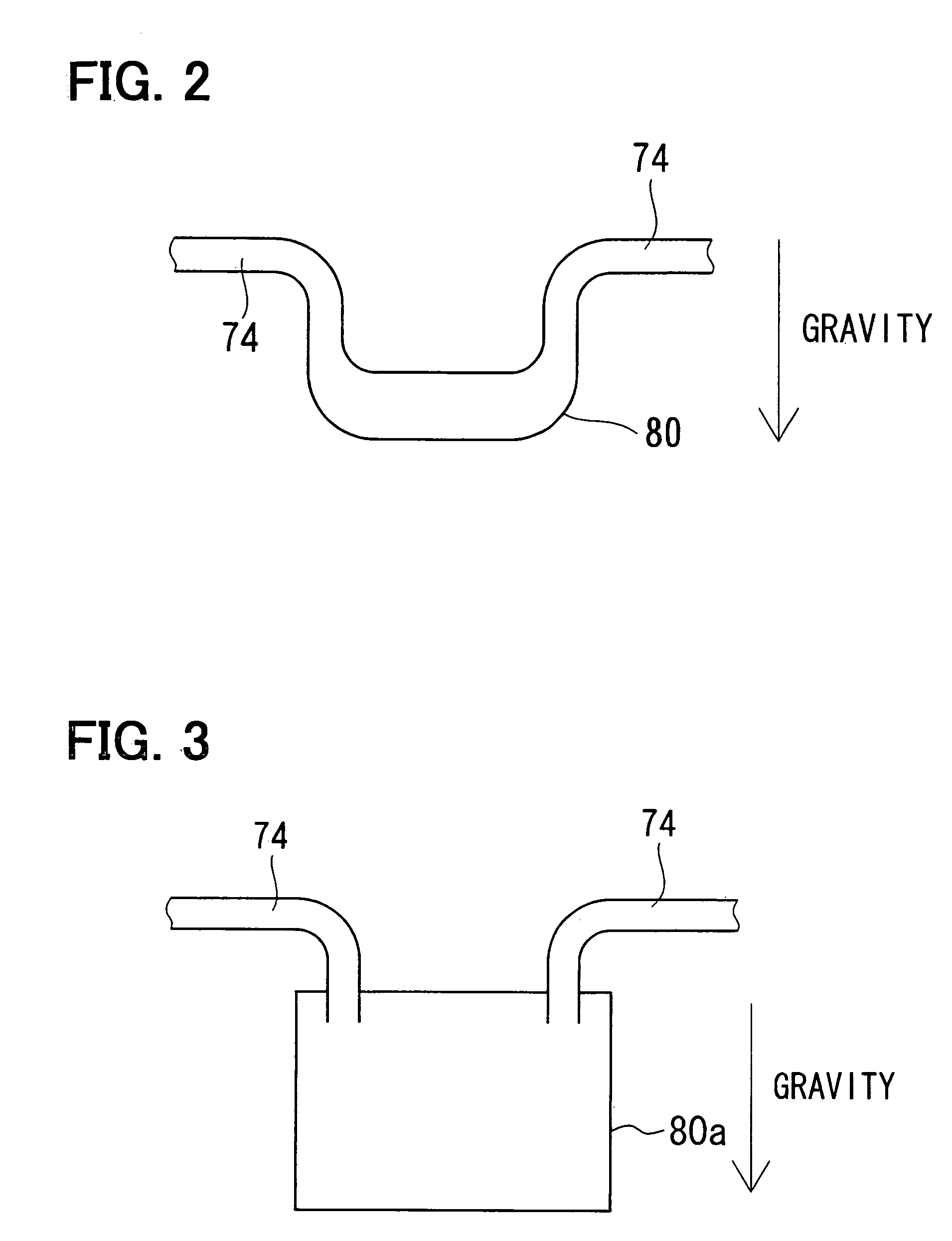
[0018]the present invention will be described with reference to FIGS. 1-3. The present invention is applied to an engine system for a Diesel engine in the embodiments. However, the present invention can be applied also to an engine system for a gasoline engine.

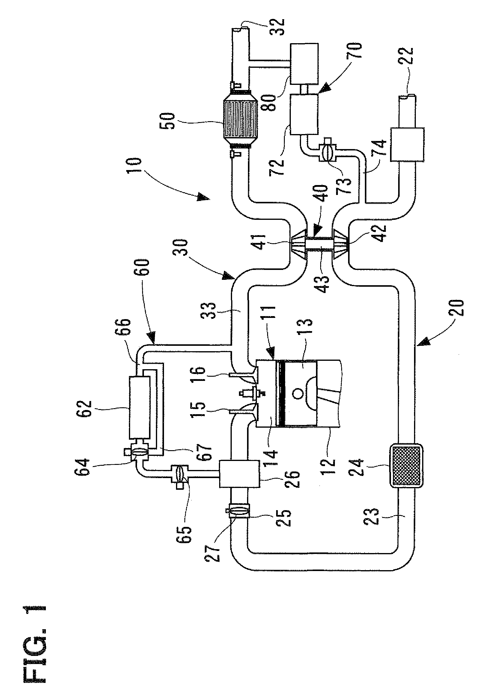
[0019]FIG. 1 shows an engine system 10. The engine system includes an engine 11, an intake system 20, an exhaust system 30, a supercharger 40, an exhaust gas cleaner 50, a high pressure EGR (Exhaust Gas Recirculation is referred to as EGR in this specification) system 60, and a low pressure EGR system 70. The engine 11 includes plural cylinders 12. Bach cylinder 12 has a piston 13 reciprocating in its axial direction, forming a combustion chamber 14 between the piston 13 and the cylinder 12.

[0020]The intake system 20 introduces air into the engine 11. The intake system 20 forms an intake passage 23 which is open outside at one end and connected to the combustion chamber 14 at the other end. In the intake passage 23, an intake ...

second embodiment

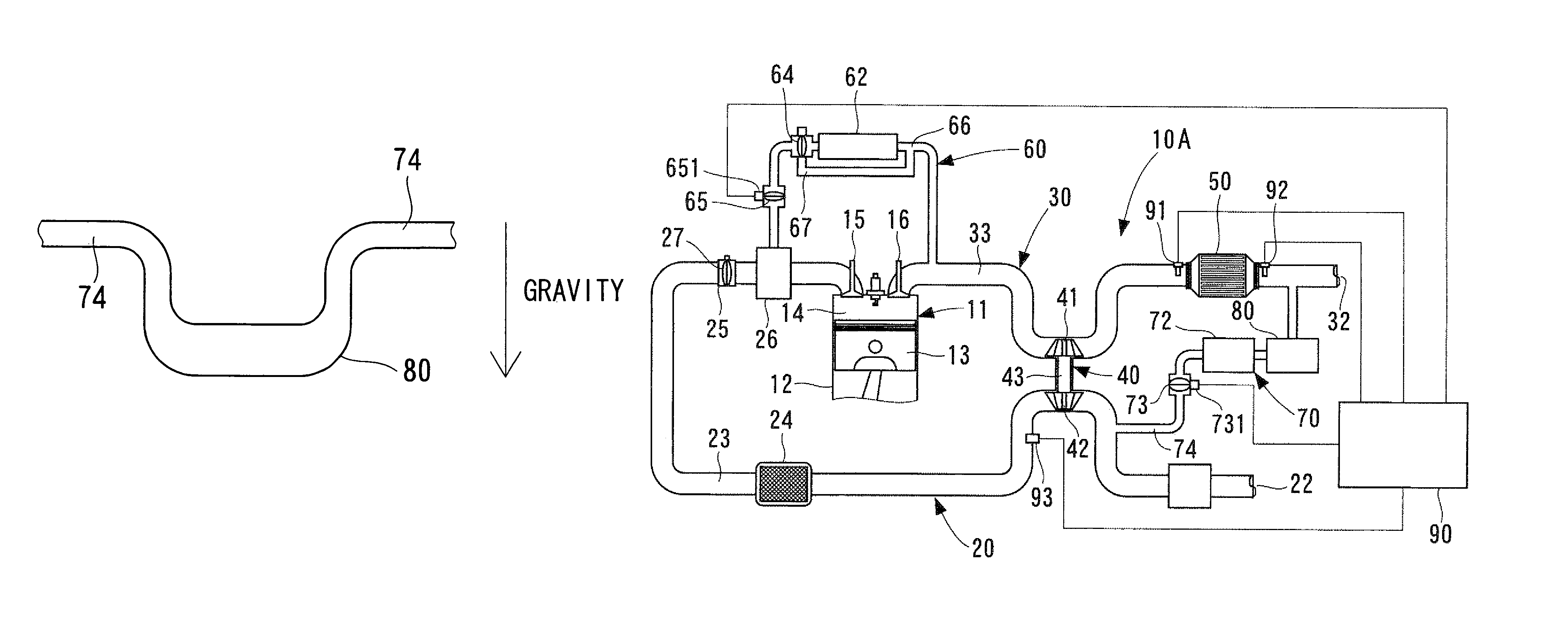
[0032]With reference to FIG. 4, the present invention will be described. In this embodiment, an electronic control unit (ECU) 90 and pressure sensors 91, 92 and 93 are additionally included in an engine control system 10A. The ECU 90 is composed of a microcomputer including a CPU, a ROM and a RAM. The ECU 90 controls an entire operation of the engine system 10A.

[0033]The pressure sensor 91 disposed at an upstream end of the exhaust gas cleaner 50 detects a pressure of the exhaust gas entering the exhaust gas cleaner 50 and sends an electrical signal representing the detected pressure to the ECU 90. The pressure sensor 92 disposed at an downstream end of the exhaust gas cleaner 50 detects a pressure of the exhaust gas flowing out from the exhaust gas cleaner 50 and sends an electrical signal representing the detected pressure to the ECU 90. The pressure sensor 93 disposed in the intake passage 23 at a downstream portion of the compressor 42 detects a pressure of the intake air superc...


PUM


Abstract

A low pressure EGR system includes a low pressure EGR passage connecting a downstream portion of an exhaust gas cleaner disposed in an exhaust passage to an upstream portion of a supercharger compressor disposed in an intake passage. A device for trapping foreign particles contained in EGR gas to be recirculated is disposed in the low pressure EGR passage. The trapping device may be positioned lower than the passage connected thereto so that foreign particles drop into the device by their own weight. A cross-sectional area of the trapping device may be made larger than that of the passage so that the flow speed of the EGR gas is reduced in the trapping device and the foreign particles are easily trapped. A valve for closing the low pressure EGR passage may be disposed therein to stop EGR when malfunctions are detected in the exhaust gas cleaner or the supercharger.

Description

CROSS-REFERENCE TO RELATED APPLICATION[0001]This application is based upon and claims benefit of priority of Japanese Patent Application No. 2006-336620 filed on Dec. 14, 2006, the content of which is incorporated herein by reference.BACKGROUND OF THE INVENTION[0002]1. Field of the Invention[0003]The present invention relates to an exhaust gas recirculation system for an internal combustion engine. The exhaust gas recirculation system is referred to as the EGR system in this specification.[0004]2. Description of Related Art[0005]An EGR system for recirculating part of exhaust gas of an internal combustion engine to an intake system has been known hitherto. Two types of the EGR systems have been used. One is a high pressure EGR system in which a high pressure exhaust gas exhausted from a combustion chamber is directly supplied to a downstream portion of a throttle. The other one is a low pressure EGR system in which exhaust gas (a relatively low pressure gas) passed through an exhaus...

Claims


Application Information

Patent Timeline
Patent Type & Authority Patents(United States)
IPC IPC(8): F02B33/44F02M25/06F02M25/07
CPCF02M25/0707F02M25/0718F02M25/0728F02M25/0732F02M25/074F02M25/0709F01N11/002F01N2560/08F02B37/00Y02T10/121F02M26/35F02M26/05F02M26/06F02M26/15F02M26/24F02M26/25
Inventor TAKEMOTO, EIJI
Owner DENSO CORP
Why Eureka
Try Eureka