

Flat belt made of elastomeric material
- Summary
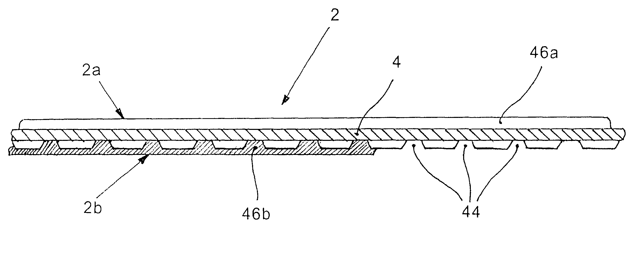
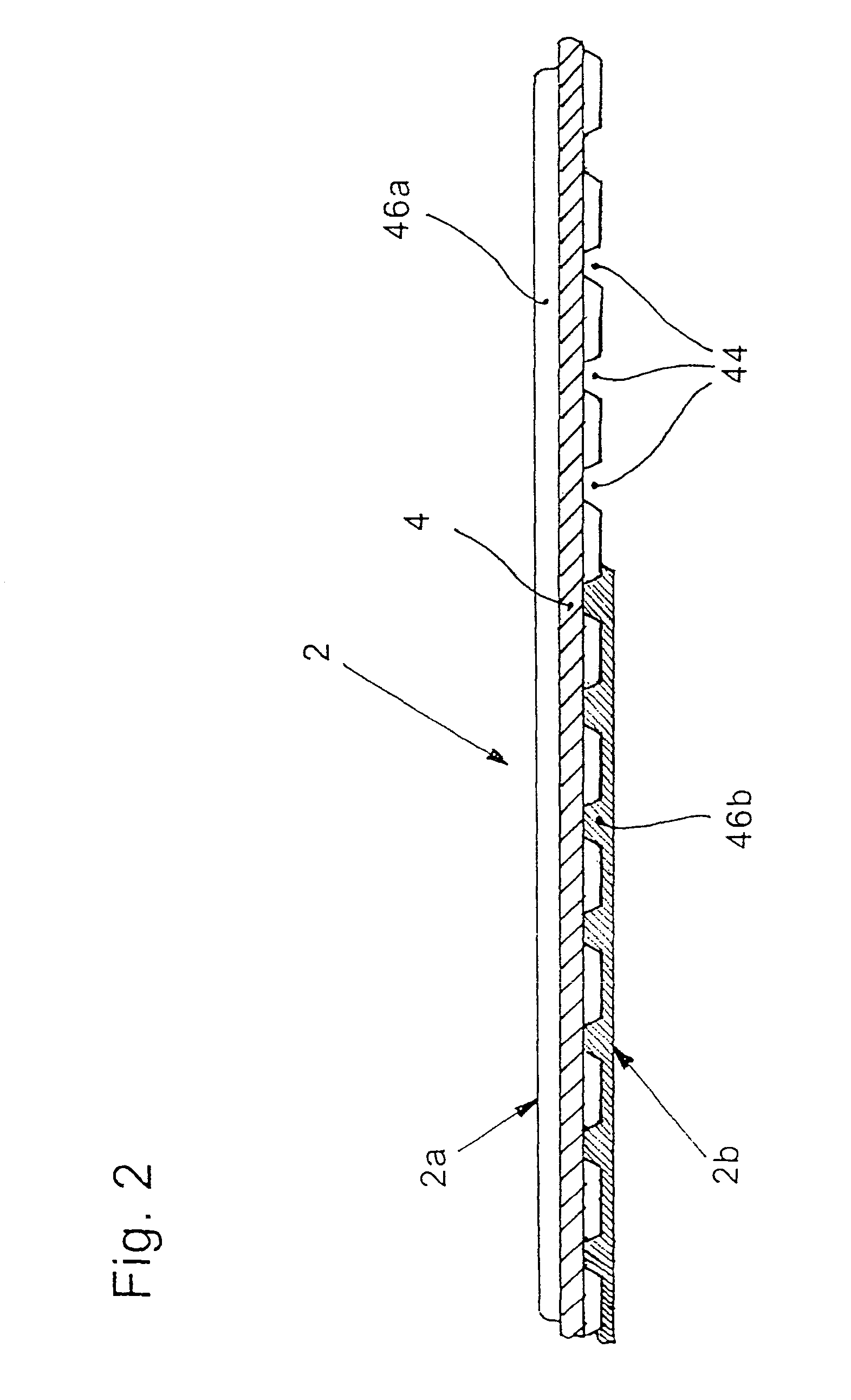
- Abstract
- Description
- Claims
- Application Information
AI Technical Summary
Benefits of technology
Problems solved by technology
Method used
Image

Examples
Embodiment Construction
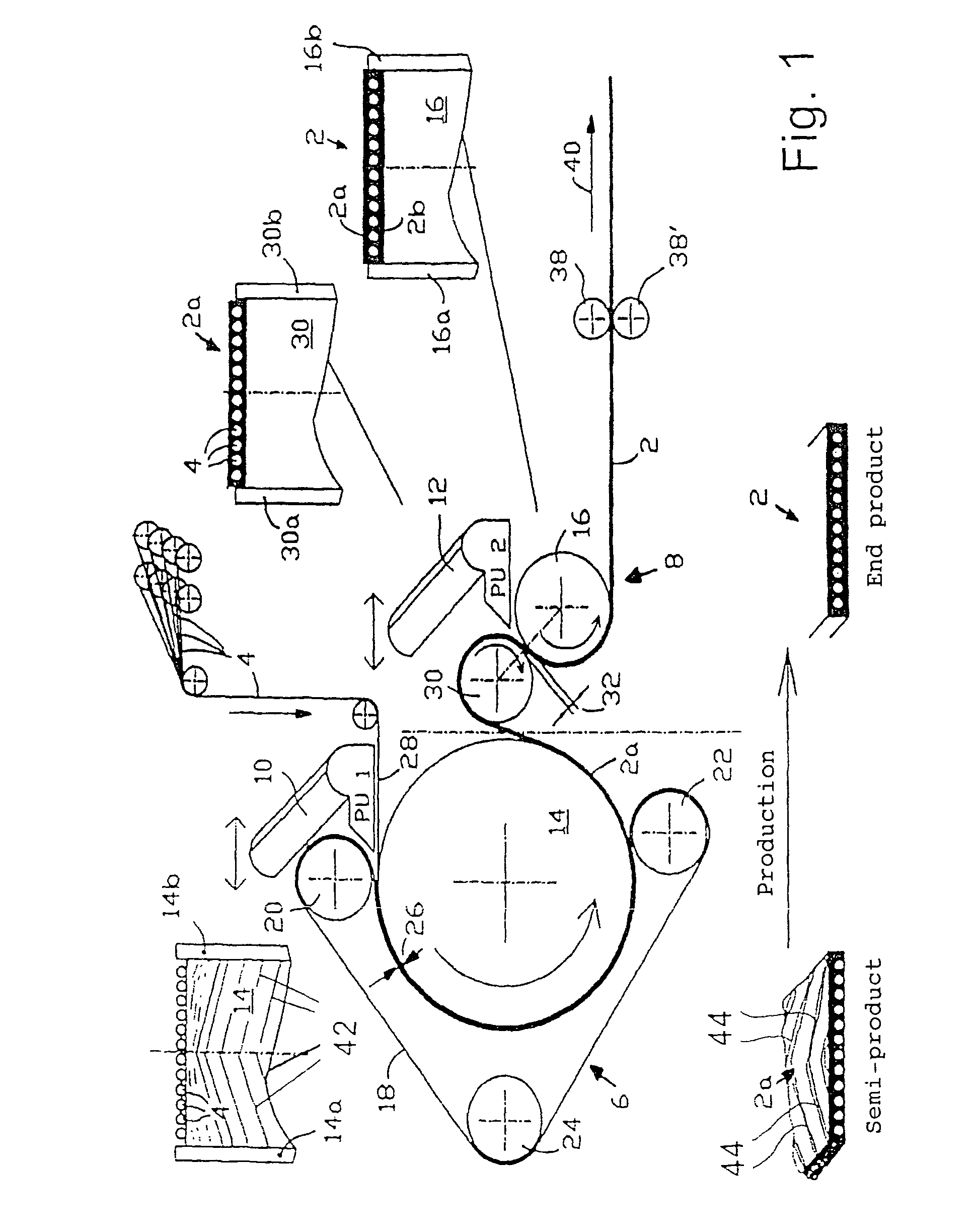
[0022]The arrangement shown in FIG. 1 for making a belt 2 reinforced with reinforcement carriers 4 has two stations: a first station 6 and a second station 8. The first station 6 functions to make a first belt part 2a and comprises a mold drum 14, which is rotatable in the counterclockwise direction, and a continuous mold belt 18 which slings around a part of the mold drum 14. The ends of the part are defined by an upper pressure roller 20 and a lower pressure roller 22 in combination with a tensioning roller 24. A hollow mold space 26 is formed between the segment of the mold belt 18 and the peripheral surface of the mold drum 14 disposed therebelow. With the aid of the tensioning roller 24, the contact pressure of the mold belt 18 on the mold drum 14 can be adjusted.
[0023]Furthermore, the first station 6 includes an extruder 10 and a filament feed 28.
[0024]To manufacture the first belt part 2a on the first station 6, a plasticatable synthetic material (for example, PU) is outputte...
PUM
| Property | Measurement | Unit |
|---|---|---|
| Elastomeric | aaaaa | aaaaa |
| Tension | aaaaa | aaaaa |
Abstract
Description
Claims
Application Information