Semiconductor device with vertical trench and lightly doped region
a technology of semiconductor and trench, which is applied in the direction of semiconductor devices, semiconductor/solid-state device manufacturing, electrical apparatus, etc., can solve the problems of unsuitable manpower for the power mosfet, and achieve the effects of low on-resistance, scaling-down, and increasing the concentration of drift layers
- Summary
- Abstract
- Description
- Claims
- Application Information
AI Technical Summary
Benefits of technology
Problems solved by technology
Method used
Image
Examples
first embodiment
[0041]The semiconductor device according to a first embodiment of the present invention is described with reference to FIG. 1 to FIG. 5.
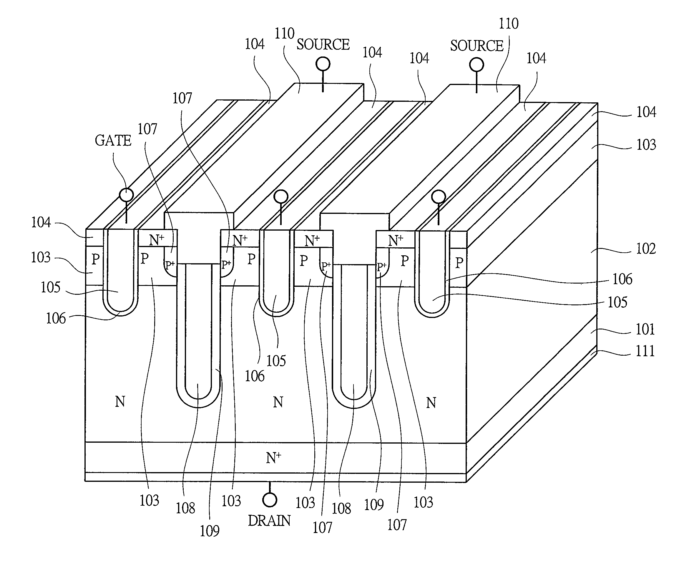
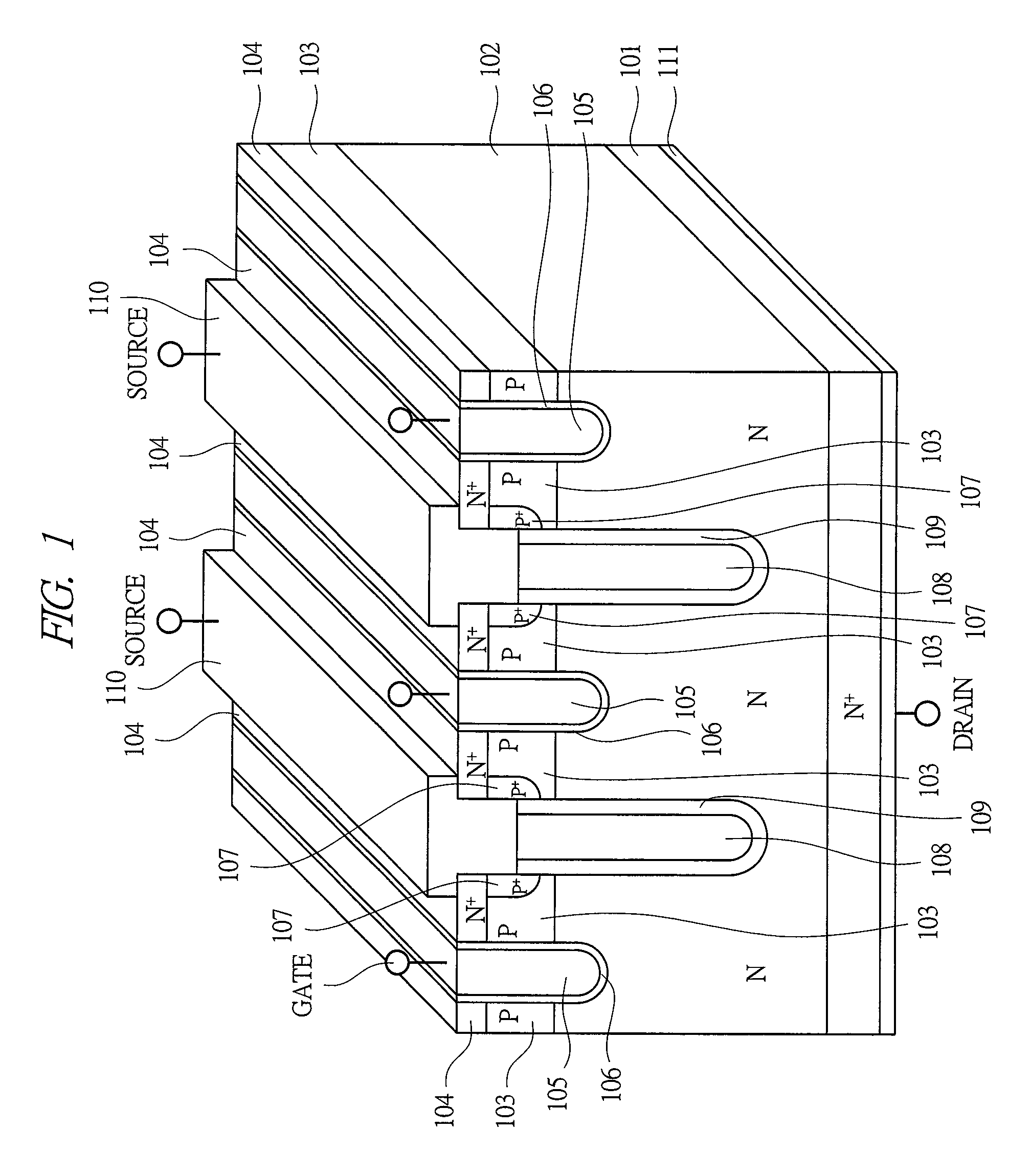
[0042]FIG. 1 shows an example of a structure of a vertical trench MOSFET with low breakdown voltage having a RESURF structure according to the first embodiment of the present invention.
[0043]In the vertical trench MOSFET according to the first embodiment, an N type epitaxial region 102, a channel region 103, a source region 104, a gate electrode 105, a gate insulator 106, a body contact region 107, a trench-buried source electrode 108, a trench-buried source insulator 109, and the like are formed on an N+ type substrate 101, and a source electrode 110 is formed on the front surface thereof and a drain electrode 111 is formed on the rear surface thereof.
[0044]More particularly, the N type epitaxial region 102 formed on the upper surface of the N+ type substrate 101 having the drain electrode 111 on the lower surface thereof, a gate trench extending f...
second embodiment
[0061]A semiconductor device according to a second embodiment of the present invention is described with reference to FIG. 6 and FIG. 7.
[0062]FIG. 6 shows an example of a structure of the vertical trench MOSFET with low breakdown voltage having the RESURF structure according to the second embodiment of the present invention.
[0063]The vertical trench MOSFET according to the second embodiment is different from the first embodiment in the following points. The present embodiment is characterized in that the distance from the front surface to the bottom of the gate trench is equal to the distance from the front surface to the bottom of the field trench, the gate insulator of the bottom surface in the gate trench is thicker than that of the side surface in the gate trench, and the process of forming the gate trench and the process of forming the field trench are performed at the same time. Also, the present embodiment is characterized in that a thickness of a gate insulator 201 of the bo...
third embodiment
[0070]A semiconductor device according to a third embodiment of the present invention is described with reference to FIG. 8.
[0071]FIG. 8 shows an example of a structure of the vertical trench MOSFET with low breakdown voltage having the RESURF structure according to the third embodiment of the present invention.
[0072]The vertical trench MOSFET according to the third embodiment is different from the first embodiment in the following point. The present embodiment is characterized in that a more highly-doped body contact region 302 than the channel region 103 is selectively formed on the front surface of the channel region 103.
[0073]More specifically, in the vertical trench MOSFET according to the present embodiment, on the front surface of the channel region 103, the body contact region 302 is formed so as to be alternately disposed with the source region 301 in a backward direction. In this manner, in addition to the effect of the first embodiment, the sufficient avalanche resistance...
PUM
 Abstract
Description
Claims
Application Information
 - R&D
- Intellectual Property
- Life Sciences
- Materials
- Tech Scout
- Unparalleled Data Quality
- Higher Quality Content
- 60% Fewer Hallucinations
Browse by: Latest US Patents, China's latest patents, Technical Efficacy Thesaurus, Application Domain, Technology Topic, Popular Technical Reports.
© 2025 PatSnap. All rights reserved.Legal|Privacy policy|Modern Slavery Act Transparency Statement|Sitemap|About US| Contact US: help@patsnap.com


