Spin momentum transfer MRAM design

a technology of momentum transfer and random access memory, applied in the field of spin momentum transfer random access memory (smtmram) cells, can solve the problems of thermal agitation, cell can still be accidentally programmed, and difficulty in scaling,

Inactive Publication Date: 2011-04-19
TAIWAN SEMICON MFG CO LTD
View PDF8 Cites 49 Cited by
  • Summary
  • Abstract
  • Description
  • Claims
  • Application Information

AI Technical Summary

Benefits of technology

[0020]A first object of this invention is to provide a STT-MRAM device of the spin torque transfer (STT) variety, in either an MTJ or GMR configuration, in which the free layer responds differently during read operations and write operations so the critical switching current can be reduced.
[0024]A fifth object of the present invention is to provide such a variably coupled free layer whose critical current, Ic, can be further reduced by employing a coupled periodically laminated structure.
[0026]Referring to FIG. 6b, there is shown a cell with the same basic free layer (25), intermediate layer (26) and pinned layer (27) as shown in FIG. 6a, but the free layer (25) is a periodic lamination of four [ferromagnetic layer / coupling valve layer] laminates, labeled (251), (252), (253) and (254) and an additional ferromagnetic layer (255) adjacent to the intermediate layer (26) to complete the periodic structure. This structure would reduce the required switching current by an additional factor of one fourth.

Problems solved by technology

However, these cells can still be accidentally programmed, causing an error.
Another shortcoming of this approach to programming cells is a scaling difficulty: as cell dimensions become smaller, Hs increases, requiring a higher current to produce the required switching.
However, as the cell dimensions become smaller, thermal agitation may perturb the stored information (i.e., change the magnetization of the free layer).
But increasing Mst will increase Ic, which is undesireable.
Thus it is a challenge to have a low value of Ic for reliable writing, yet to maintain the thermal stability of stored data.

Method used


Image

  • Spin momentum transfer MRAM design
  • Spin momentum transfer MRAM design
  • Spin momentum transfer MRAM design

Examples


Embodiment Construction

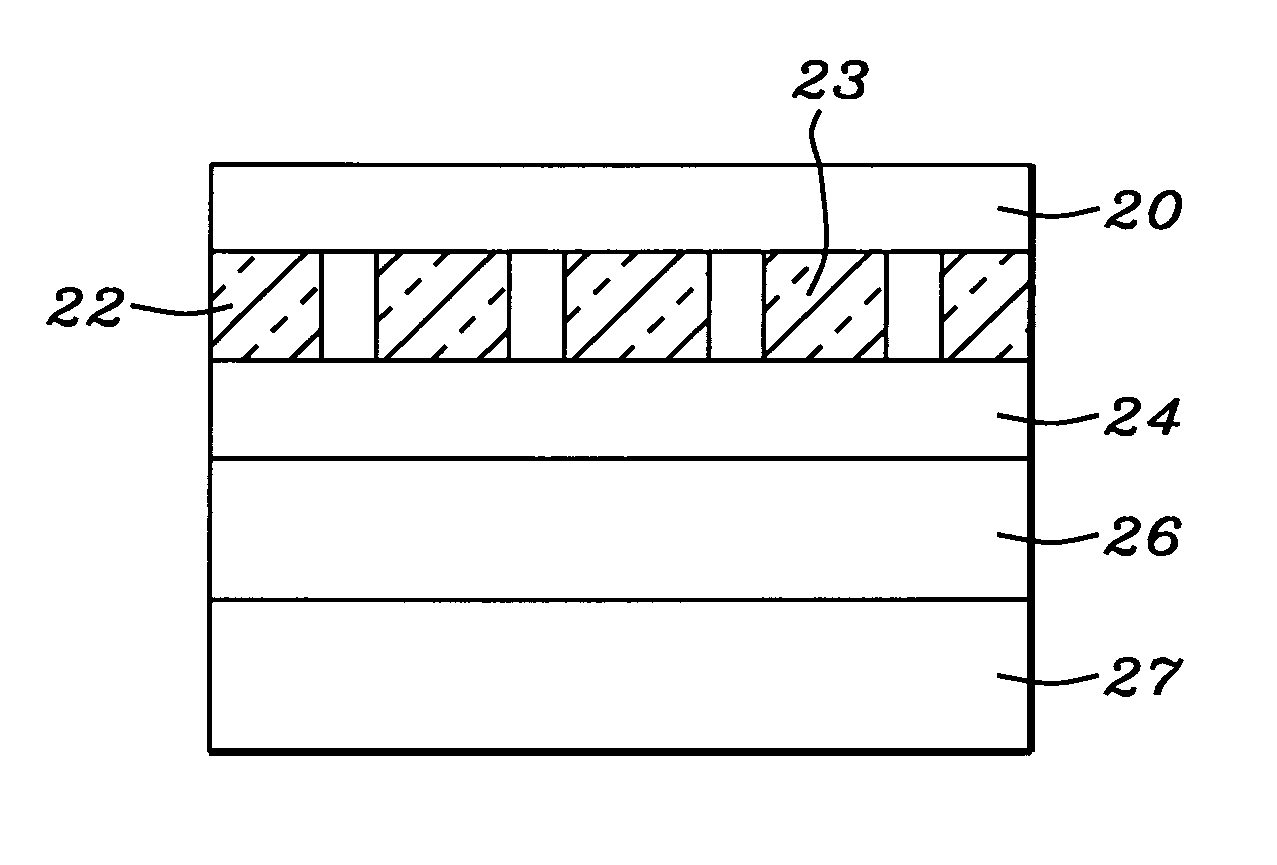
[0044]The preferred embodiment of the present invention is an MRAM device of the spin-transfer MTJ variety, incorporating an STT MTJ cell element, in which the free layer is formed as a pair of magnetic (preferably ferromagnetic) layers, called herein magnetic storage layers, coupled by a coupling valve layer. In this construction the preferable ferromagnetic layers are strongly exchanged coupled in a parallel (ferromagnetic) magnetization configuration when the cell temperature is below the Curie temperature of the coupling valve layer, but are magnetostatically coupled in an anti-parallel configuration of magnetizations, when the cell temperature is above the Curie temperature. The exchange coupled state is advantageous for storing and reading information, where the magnetization of the free layer should be highly stable, whereas the magnetostatically coupled state is advantageous for the writing of information, where the magnetization of the free layer is required to be changed a...


PUM


Abstract

We describe the structure and method of formation of a STT MTJ or GMR MRAM cell element that utilizes transfer of spin torque as a mechanism for changing the magnetization direction of a free layer. The critical current is reduced by constructing the free layer as a lamination comprising two ferromagnetic layers sandwiching a coupling valve layer. When the Curie temperature of the coupling valve layer is above the temperature of the cell, the two ferromagnetic layers are exchange coupled in parallel directions of their magnetization. When the coupling valve layer is above its Curie temperature, it no longer exchange couples the layers and they are magnetostatically coupled. In the exchange coupled configuration, the free layer serves to store data and the cell can be read. In its magnetostatically coupled configuration, the cell can be more easily written upon because one of the layers can assist the spin torque transfer by its magnetostatic coupling. If the free layer is formed as a multi-layered lamination of N periodically repeating combinations of a ferromagnetic layer and a coupling valve layer, the critical current can be reduced by a factor of N.

Description

BACKGROUND OF THE INVENTION[0001]1. Field of the Invention[0002]This invention relates generally to a spin momentum transfer random access memory (SMT-MRAM) cell formed in either a magnetic tunneling junction (MTJ) or GMR Spin Valve (SV) configuration, using a spin momentum transfer (SMT) effect to change the magnetization of a free layer. In particular, it relates to a free layer design to enhance the properties of such a cell.[0003]2. Description of the Related Art[0004]The conventional magnetic tunneling junction (MTJ) or GMR Spin Valve (GMR / SV) device is a form of ultra-high magnetoresistive (MR) device in which the relative orientation of the magnetic moments of parallel, vertically separated magnetized layers, controls the flow of spin-polarized electrons tunneling either through a very thin dielectric layer (in the MTJ case) or through a thin conducting layer of a transitional metal (in the GMR / SV case) formed between those layers.[0005]When injected electrons pass through th...

Claims


Application Information

Patent Timeline
Patent Type & Authority Patents(United States)
IPC IPC(8): G11C11/06
CPCB82Y10/00B82Y25/00G11C11/16H01F10/3254H01F10/3272H01F10/3259H01L43/08H01L43/12H01F10/3286H01F10/329H01L27/228G11C11/1675H10B61/22H10N50/10H10N50/01
Inventor MIN, TAI
Owner TAIWAN SEMICON MFG CO LTD
Why Eureka
Try Eureka