
System and method of controlling power to a non-motor load

a non-motor load and power control technology, applied in the direction of electronic commutation motor control, motor/generator/converter stopper, dynamo-electric converter control, etc., can solve the problems of load to load, current power conditioners often trip, and conventional controllers cannot predict load transitions and adjust accordingly

Active Publication Date: 2011-04-26
EATON INTELLIGENT POWER LTD
View PDF94 Cites 49 Cited by
  • Summary
  • Abstract
  • Description
  • Claims
  • Application Information

AI Technical Summary

Benefits of technology

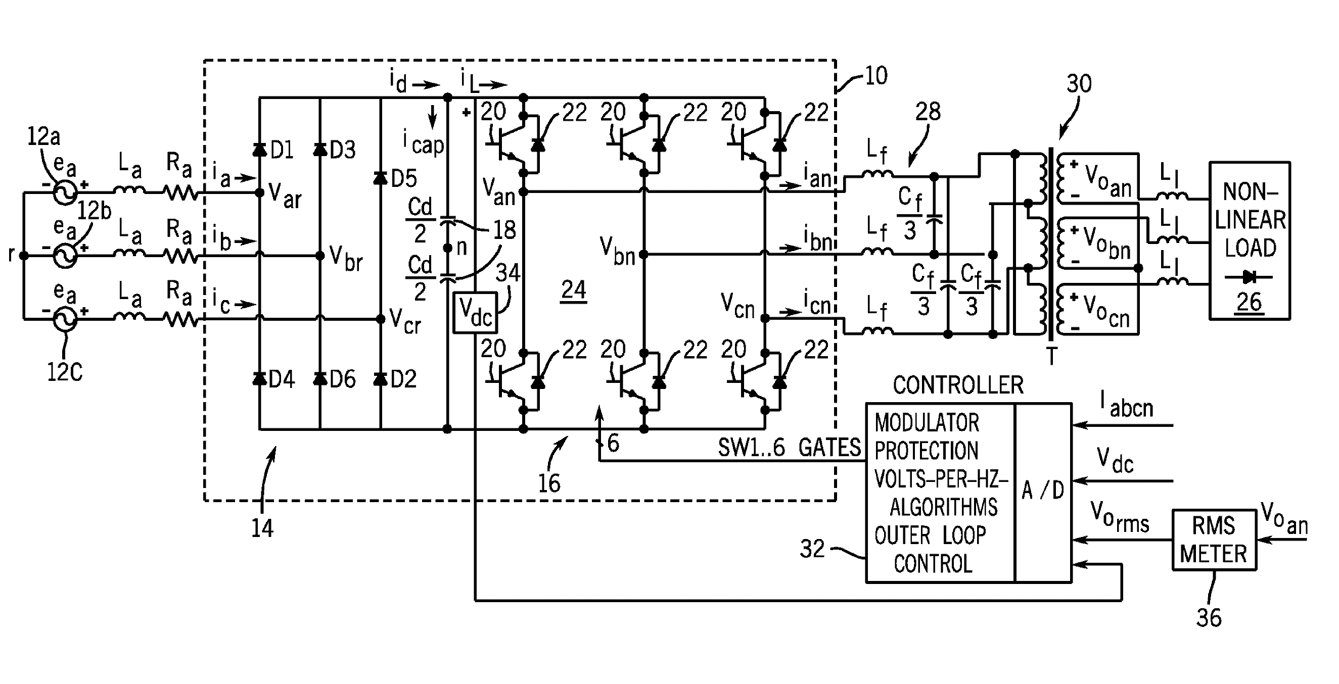
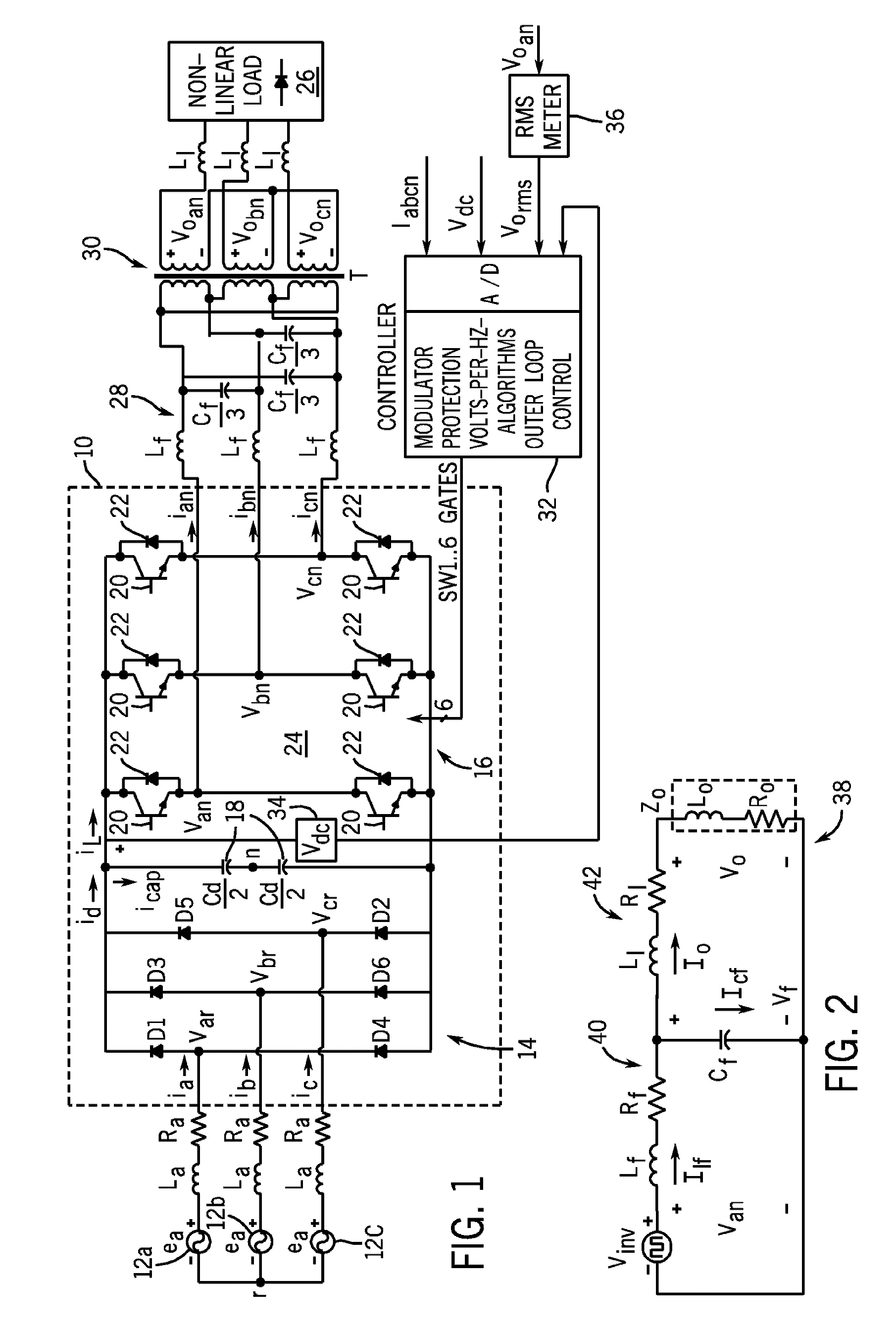
The present invention provides a system and method for controlling power to a non-motor load. The system includes a motor drive with a voltage feedback circuit that monitors the DC bus voltage and adjusts the power conditioning scheme accordingly to maintain near steady-state load conditions in response to a transient load condition. The motor drive has a controller that controls the switching of the at least one switch to maintain the load voltage regulation. The power conditioner has a rectifier bridge, inverter, filter, and PID controller to regulate the power output to the load. The method includes detecting a change in voltage across the DC bus and dynamically controlling the switching of the switch array of the motor drive to achieve load voltage regulation. The technical effects of the invention include maintaining stable load conditions, reducing harmonic distortion, and improving power delivery efficiency.

Problems solved by technology

However, current power conditioners often trip, or cause the load to trip, when strict voltage and current constraints are not met.
However, because of the poor and finite response time of the RMS voltmeters that provide feedback as to load voltage to the PI controller of the power condition, it can become problematic for the controller to determine and effectuate the appropriate corrective measures in the switching of the IGBTs to prevent failure of the load.
In other words, conventional controllers cannot predict load transitions and adjust accordingly.
While generally successful during near steady-state conditions, the response times of voltmeters are such that transient load conditions cannot be addressed expeditiously.
As such, appropriate correction in the power conditioning cannot be timely executed to prevent tripping of the scanner.
In short, transient load conditions can cause under-voltage and over-voltage conditions to occur; both of which can cause the non-motor load to fail.
Such a 40V drop can cause the scanner to fail.
In other words, the scanner needs minimally more than 440VDC to maintain operation and, as such, when a 40V drop occurs, the scanner can become under-powered and, ultimately, fail—leading to scanner down time, service calls, and the like.
Similarly, the significant inrush of current can cause the scanner or other non-motor load to trip.
As such, the inrush of current when the scanner is turned ON, i.e., the load applied, may cause tripping of the scanner's internal breaker.
This also results in scanner down time, service calls, and the like.
A line-interactive UPS, while generally effective in load protection, would be connected in parallel as a backup to utility power and cannot provide power for continuous operation of a medical imaging scanner, such as a magnetic resonance (MR), x-ray, or computed tomography (CT) scanner.
Additionally, while a double-conversion UPS provides substantial load protection, isolation from upstream distribution systems, wide input voltage tolerances, and load voltage and frequency regulation, such UPS devices are quite costly and generally less efficient than motor drives.

Method used


Image

  • System and method of controlling power to a non-motor load
  • System and method of controlling power to a non-motor load
  • System and method of controlling power to a non-motor load

Examples


Embodiment Construction

Referring now to FIG. 1, a power conditioner 8 having an adjustable speed motor drive 10 is shown. The adjustable speed drive (ASD) is designed to receive a three AC power input, rectify the AC input, and perform a DC / AC conversion of the rectified segment into a three-phase alternating voltage of variable frequency and amplitude that is supplied to a load. In a preferred embodiment, the ASD operates according to an exemplary volts-per-hertz characteristic. In this regard, the motor drive provides voltage regulation of ±1% in steady state with less than 3% total harmonic distortion, +0.1 Hz in output frequency, and fast dynamic step load response over a full load range.

In an exemplary embodiment, a three-phase AC input 12a-12c is fed to a three-phase rectifier bridge 14. The input line impedances are equal in all three phases. The rectifier bridge 14 converts the AC power input to a DC power such that a DC bus voltage is present between the rectifier bridge 14 and a switch array 16....


PUM


Abstract

A motor drive for conditioning power to be delivered to a non-motor load includes a voltage feedback circuit that monitors a DC bus voltage and, based on changes in the DC bus voltage, adjusts a power conditioning scheme such that near steady-state load conditions are maintained in response to a transient load condition. The voltage feedback circuit has a voltage sensor that provides voltage feedback to a controller that determines what changes in power conditioning are needed in response to a transient load condition that manifests itself in a change in DC bus voltage.

Description

BACKGROUND OF THE INVENTIONThe present invention relates generally to power conditioning and, more particularly, to a system and method of controlling power to a non-motor load using a motor drive.Motor drives are frequently used in industrial applications to condition power and otherwise control electric driven motors such as those found with pumps, fans, compressors, cranes, paper mills, steel mills, rolling mills, elevators, machine tools, and the like. Motor drives typically provide a volts-per-hertz control and have greatly improved the efficiency and productivity of electric driven motors and applications. Increasingly, motor drives are taking the form of adjustable-speed drives (ASD) that are adept at providing variable speed and / or variable torque control to an electric driven motor. Heretofore, motor drives have been used solely to control or otherwise condition power to a motor load.Power to non-motor loads is usually controlled through a power conditioner that is specific...

Claims


Application Information

Patent Timeline
Patent Type & Authority Patents(United States)
IPC IPC(8): H02P27/04
CPCH02M7/53875H02P29/026H02P27/06H02M2001/0022H02M1/0022
Inventor LEE, KEVINAHLGREN, JYRKI K.WALLACE, IAN T.DORING, THOMAS M.
Owner EATON INTELLIGENT POWER LTD
Learn More