Distributed system of electrical generators utilizing wind driven natural motion of trees

a distributed system and generator technology, applied in the direction of electric generator control, machines/engines, mechanical equipment, etc., can solve the problems of large networks of small generators powered by swaying trees, no approach has been made to use wind driven swaying trees or large networks of small generators. , to achieve the effect of reducing environmental impact, reducing maintenance costs, and simple construction

Inactive Publication Date: 2011-05-03
REES HOWARD DAVID +1
View PDF10 Cites 6 Cited by
  • Summary
  • Abstract
  • Description
  • Claims
  • Application Information

AI Technical Summary

Benefits of technology

[0015]An important object of this invention is to provide a new and improved power generating system which is of simple construction and will operate with a minimum of attention and with minimal environmental impact.

Problems solved by technology

There are renewable energy systems powered by wind turbines, by water waves, by human movement and even by the small movements of transportation bridges, but no approach until now makes use of wind driven swaying trees or large networks of small generators powered by swaying trees.

Method used


Image

  • Distributed system of electrical generators utilizing wind driven natural motion of trees
  • Distributed system of electrical generators utilizing wind driven natural motion of trees
  • Distributed system of electrical generators utilizing wind driven natural motion of trees

Examples


Embodiment Construction

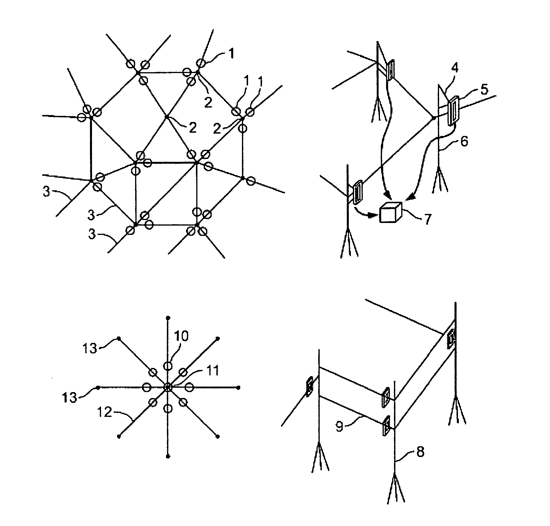
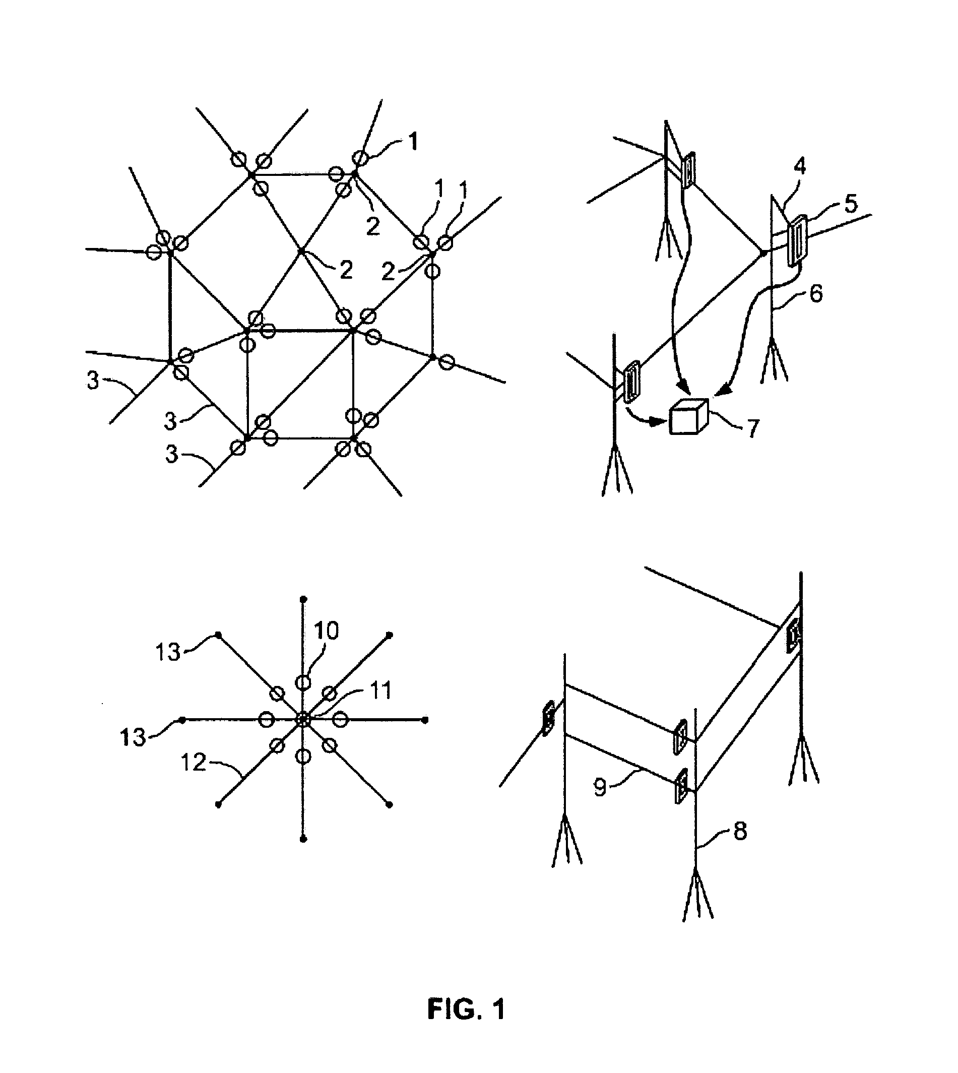
[0123]FIG. 1 are schematic diagrams of examples of how various stands of trees might be networked or “farmed” and of how the pull-retract generators (PRGs) might be configured. Points 1.-3. refer to a system that presumes all trees are of the same species and more or less of the same age, size and flexibility. These trees would be trimmed (i.e., some branches might be cut and some smaller trees may be removed) so that their saddles could all be located at a uniform height and the distribution of PRGs would be that of a fairly uniform lattice. Points 10.-13. refer to a possible configuration for a stand of trees that includes some older, larger trees and others that are young, the older and larger more rigid and the younger and thinner more flexible. Points 8.-9. show how tall trees might support multiple PRGs. Coppiced units can be farmed separately. As is nature, the variety of e-Tree farm configurations is unlimited.

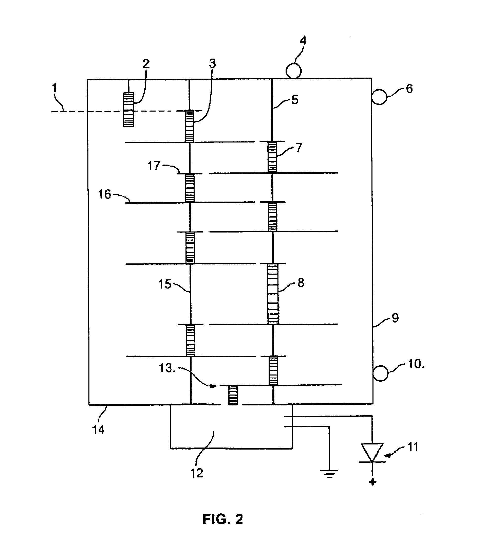
[0124]FIG. 2-FIG. 6 are diagrams of a pull-retract generator (PRG...


PUM


Abstract

A distributed system of electrical generators utilizing wind driven natural motion of trees includes pull-retract generators deriving torque from the back and forth swaying of neighboring trees and cables, wherein one set of cables acting as support and the other acting as a spring-tensioned flexible rack that drives the pinion gear of the pull-retract generator and also supports the pull-retract generator between the trees. The cables are attached to the pull-retract generators and provide the tension required to support and retract the pull-retract generator mechanism. Tree saddles attach the pull-retract generator cabling to the trees. As the trees sway independently the separations between the trees fluctuate periodically and the pull-retract generators convert these fluctuations into rotational forces that drive the generators. The pull-retract generators make use of a flexible rack and pinion design to convert the relative tree motion into torque and achieves the requisite RPM by cascading a sequence of large-small gear pairs, one such pair in each pull-retract generator utilizing a one-way clutch torque converter, ultimately meshing with a small gear on the generator shaft. Springs are used to return the pull-retract generators to their neutral positions when the trees are stationary and maintain cable tautness when the tree separation periodically lessens by tensioning the rack and pinion cable. The electrical energy derived from the asynchronous motions of the trees, is independent of the direction of the wind and is integrated with other pull-retract generators through rectifiers and to external electrical systems through the use of existing technologies that regulates, conditions and controls the electrical output.

Description

CROSS-REFERENCE TO RELATED APPLICATIONS[0001]NONEFEDERALLY SPONSORED RESEARCH[0002]NONESEQUENCE LISTING[0003]NONEFIELD OF THE INVENTION[0004]The present invention relates to the design of a renewable energy system that comprises distributed networks of electrical generators which derive their power from the natural, wind driven swaying of trees.BACKGROUND OF THE INVENTION[0005]Energy comes in many forms and is stored in many guises. There are chemical (carbon / oxygen and hydrogen / oxygen), nuclear (fission and fusion), photo-voltaic (solar cells) and mechanical (wind, hydro-electric and geothermal) sources of energy, and people have made use of them all. Most energy sources are used to provide either electrical or mechanical power and for each there is a price to pay. Some conversion processes are more efficient than others, some are more suitable for large scale industrial or regional applications than others but almost all have environmental impacts. This invention, a distributed sy...

Claims


Application Information

Patent Timeline
Patent Type & Authority Patents(United States)
IPC IPC(8): F03D5/00
CPCF03G7/08H02K7/1853F05B2260/505F05B2260/503
Inventor REES, HOWARD DAVIDFAIGEN, MICHAEL J
Owner REES HOWARD DAVID
Why Eureka
Try Eureka