
Magnetic carrier and two-component developer

a technology of two components and carriers, applied in the field of magnetic carriers and two-component developers, can solve the problems of reducing image density, difficult in some cases to apply such carriers to the system, and inferior image formation

Active Publication Date: 2011-05-10
CANON KK
View PDF11 Cites 56 Cited by
  • Summary
  • Abstract
  • Description
  • Claims
  • Application Information

AI Technical Summary

Benefits of technology

[0010]An object of the present invention is to provide a magnetic carrier and a two-component developer which have resolved the problems discussed as above. Stated specifically, an object of the present invention is to provide a magnetic carrier and a two-component developer which have remedied blank areas, fog after leaving, carrier sticking during running, and image density variations before and after running.
[0013]The use of the magnetic carrier and two-component developer of the present invention enables sufficient remedy for blank areas, fog after leaving, and carrier sticking during running, and also lessens image density variations before and after running.

Problems solved by technology

Such a carrier, however, have had an insufficient triboelectric charge-providing ability, and hence, where images are printed after leaving for a week in a high-temperature and high-humidity environment (temperature 30° C. / humidity 80% RH), the toner may stick to non-image areas to cause a phenomenon of the formation of inferior images (i.e., fog).
Hence, it has been difficult in some cases to apply such a carrier to the system making use of an a-Si drum.
However, it has turned out that, if the Vpp is set low in using the carrier disclosed in Japanese Patent Laid-open Applications No. 2007-57943 and No. 2006-337579, a low developing performance may result to cause a decrease in image density.
It has further come about that the toner at the rear end of a halftone area is scraped off at the boundary between the halftone area and a solid area to make white lines, to cause image defects (blank areas) in which edges of solid areas stand emphasized.
However, in a high-speed machine having, e.g., a process speed of 300 mm / sec or more, which is adaptable to POD (print on-demand), there has been a problem that the blank areas occur because of an insufficient developing efficiency.
In such a high-speed machine having a process speed of 300 mm / sec or more, it has also come about in some cases that, where images are printed on 50,000 sheets in an image percentage of 1%, the resin layers at the surfaces of such magnetic carrier particles deteriorate to cause variations in image density before and after running.
However, the layer thickness of the resin is not controlled, and hence there has been a problem that, in a normal-temperature and low-humidity environment (temperature 23° C. / humidity 5% RH), the blank areas occur because of a lowering of developing efficiency when the Vpp is set low.

Method used

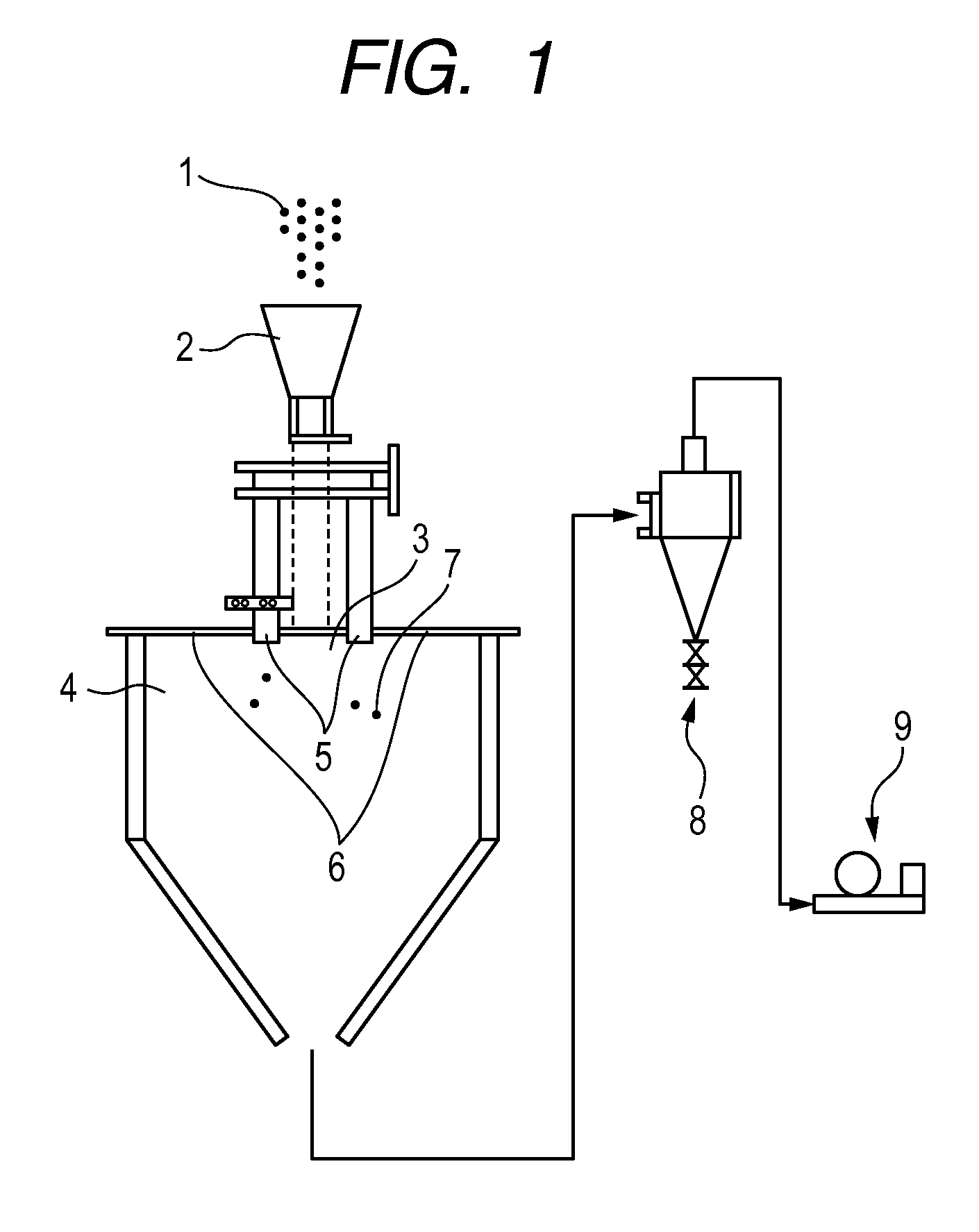
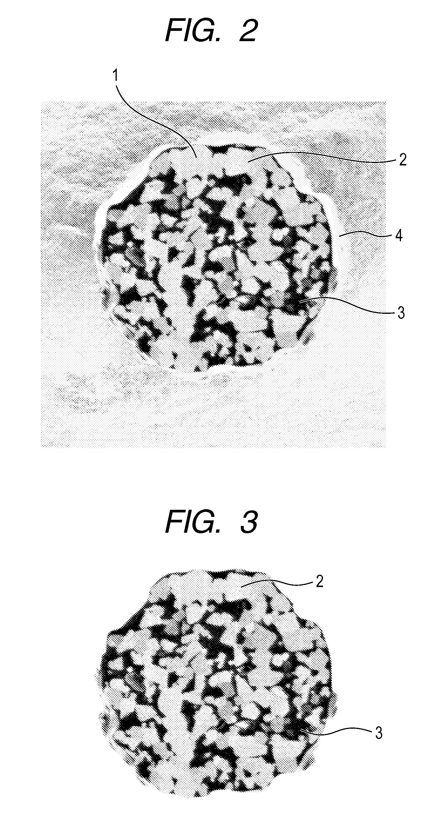

Image

  • Magnetic carrier and two-component developer
  • Magnetic carrier and two-component developer
  • Magnetic carrier and two-component developer

Examples


production example 1

Magnetic Carrier Production Example 1

Step 1

Resin Filling Method 1

[0174]100.0 parts by mass of Porous Magnetic Cores 1 were put into an agitating container of a mixing agitator (a universal agitator NDMV Model, manufactured by Dulton Company Limited). While keeping its temperature at 30° C. and while producing a vacuum, nitrogen was introduced thereinto, and Resin Solution 1 was dropwise so added under reduced pressure as to be in an amount of 12.0 parts by mass as a resin component, based on the mass of Porous Magnetic Cores 1. After its dropwise addition was completed, the agitation was continued for 2 hours as it was. Thereafter, the temperature was raised to 70° C. and the solvent was removed under reduced pressure, thus Porous Magnetic Cores 1 were filled in their core particles with a silicone resin composition having silicone resin, obtained from Resin Solution 1. After cooling, the porous magnetic cores obtained were moved to a mixing machine having a spiral blade in a rotata...

production example 2

Magnetic Carrier Production Example 2

[0176]Magnetic Carrier 2 was obtained in the same way as that in Magnetic Carrier Production Example 1 except that, in the step 1 of Magnetic Carrier Production Example 1, Porous Magnetic Cores 1 were changed for Porous Magnetic Cores 2, Resin Solution 3 was changed for Resin Solution 4 and its amount of 12.0 parts by mass was changed to 18.0 parts by mass and that, in the step 2, Resin Solution 3 was changed for Resin Solution 4, the heat treatment at a temperature of 200° C. for 2 hours was changed to heat treatment at a temperature of 100° C. for 2 hours and the air classification was not carried out.

production example 3

Magnetic Carrier Production Example 3

[0177]Magnetic Carrier 3 was obtained in the same way as that in Magnetic Carrier Production Example 1 except that, in the step 1 of Magnetic Carrier Production Example 1, Porous Magnetic Cores 1 were changed for Porous Magnetic Cores 3 and, in the step 2, the air classification was not carried out.


PUM


Abstract

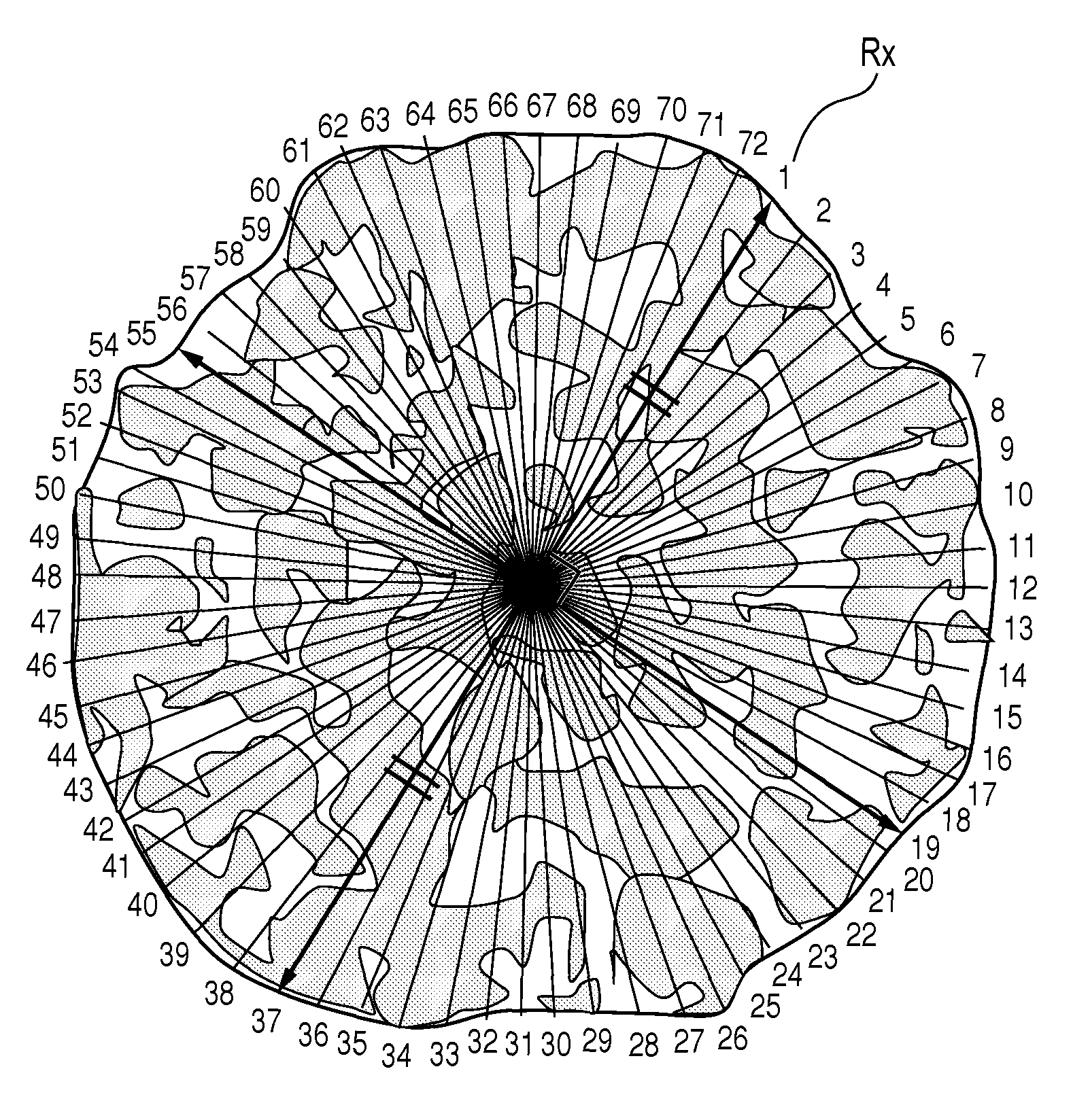
A magnetic carrier and a two-component developer are provided which have remedied blank areas, fog after leaving, carrier sticking during running, and image density variations before and after running. The magnetic carrier has magnetic carrier particles having at least porous magnetic core particles and a resin. The magnetic carrier particles satisfying the specific conditions (a), (b) and (c) where, in a reflected electron image of cross sections of the magnetic carrier particles as photographed with a scanning electron microscope, straight lines that divide a cross section of a magnetic carrier particle into 72 at intervals of 5° are drawn from a reference point of the cross section thereof toward the surface of the magnetic carrier particle; the magnetic carrier particles being contained in an amount of 60% by number or more.

Description

CROSS-REFERENCE TO RELATED APPLICATIONS[0001]This application is a continuation of International Application No. PCT / JP2009 / 064091, filed Aug. 4, 2009, which claims the benefit of Japanese Patent Application No. 2008-201072, filed Aug. 4, 2008.BACKGROUND OF THE INVENTION[0002]1. Field of the Invention[0003]This invention relates to a magnetic carrier and a two-component developer which are used in an electrophotographic system, an electrostatic recording system or an electrostatic printing system.[0004]2. Description of the Related Art[0005]In recent years, in order to achieve high image quality and high running performance which are required in electrophotography and so forth, a resin-filled carrier is proposed in which the ferrite core material having pores is filled with a resin (see Japanese Patent Laid-open Applications No. 2007-57943 and No. 2006-337579). According to these proposals, the carrier can be made low in specific gravity and this can keep, to a certain extent, infer...

Claims


Application Information

Patent Timeline
Patent Type & Authority Patents(United States)
IPC IPC(8): G03G9/00
CPCG03G9/0821G03G9/0827G03G9/107G03G9/1132G03G9/113G03G9/1131G03G9/1075G03G9/1085G03G9/08
Inventor INOUE, CHIKAFUJIKAWA, HIROYUKIISHIGAMI, KOHNAKAMURA, KUNIHIKOKOMATSU, NOZOMUENDO, TOMOKOBABA, YOSHINOBUITAKURA, TAKAYUKI
Owner CANON KK
Learn More