
Constraint based retiming of synchronous circuits

a synchronous circuit and constraint-based technology, applied in the field of constraint-based retiming of synchronous circuits, can solve the problems of difficult to predict the delay of logic gates that realize logic functions, become more difficult to perform retiming, and over-conspicuous designs that are not area efficient, etc., to achieve the effect of balancing out slack and minimizing the maximum delay

Active Publication Date: 2011-05-17
CADENCE DESIGN SYST INC
View PDF15 Cites 30 Cited by
  • Summary
  • Abstract
  • Description
  • Claims
  • Application Information

AI Technical Summary

Benefits of technology

[0014]FIG. 7 is an exemplary retiming graph representing a retiming of a c...

Problems solved by technology

However, this leads to overly conservative designs that are not area efficient.
It is also difficult to predict the delay of logic gates that realize a logic function.
As integrated circuits have become more complex, it has become more difficult to perform retiming, requiring additional time to complete the retiming process in the design flow of integrated circuits.

Method used


Image

  • Constraint based retiming of synchronous circuits
  • Constraint based retiming of synchronous circuits
  • Constraint based retiming of synchronous circuits

Examples


Embodiment Construction

[0017]In the following detailed description of the embodiments of the invention, numerous specific details are set forth in order to provide a thorough understanding of the present invention. However, it will be obvious to one skilled in the art that the embodiments of the invention may be practiced without these specific details. In other instances well known methods, procedures, components, and circuits have not been described in detail so as not to unnecessarily obscure aspects of the embodiments of the invention.

[0018]The embodiments of the invention include a method, apparatus and system for constraint based retiming of synchronous circuits.

Introduction

[0019]Retiming is a structural netlist transformation which moves registers forward and backward in the logic. Retiming has the objective to (1) minimize the clock period and to (2) minimize the number of registers either for the minimum clock period achievable by retiming or for a given clock period.

[0020]Registers can have diff...


PUM


Abstract

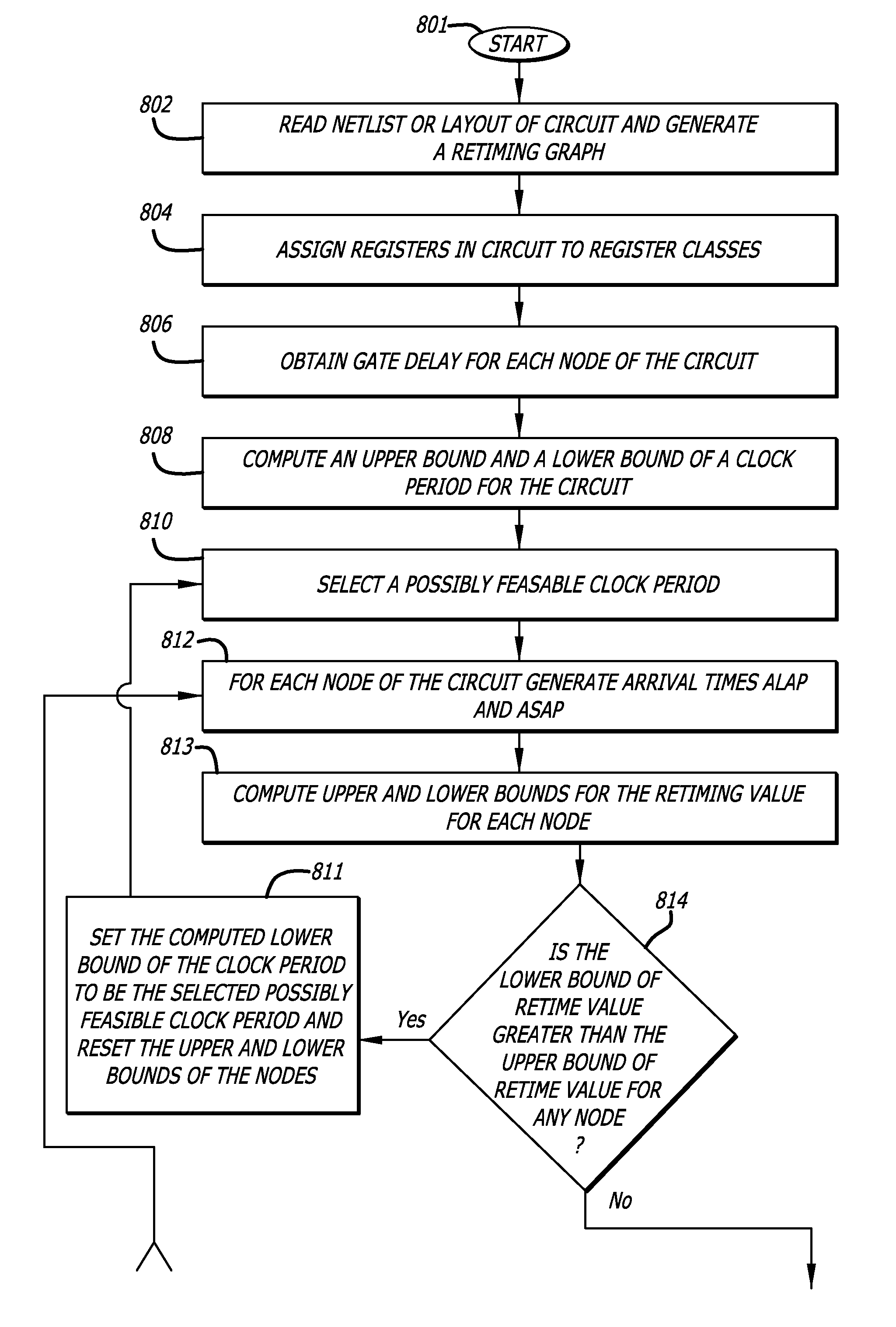
In one embodiment of the invention, a method of retiming a circuit is disclosed. The method includes computing an upper bound and a lower bound for a clock period of a clock signal to clock a circuit in response to a netlist of the circuit; selecting a potential clock period for the clock signal to clock registers of the circuit in response to the computed upper bound and the computed lower bound for the clock period; computing an upper bound and a lower bound of a retiming value for each node of the circuit to determine if a retiming of the circuit is achievable with the potential clock period; and computing the retiming value for each node of the circuit to minimize circuit area in response to the computed upper bound and the computed lower bound of the retiming value for each node.

Description

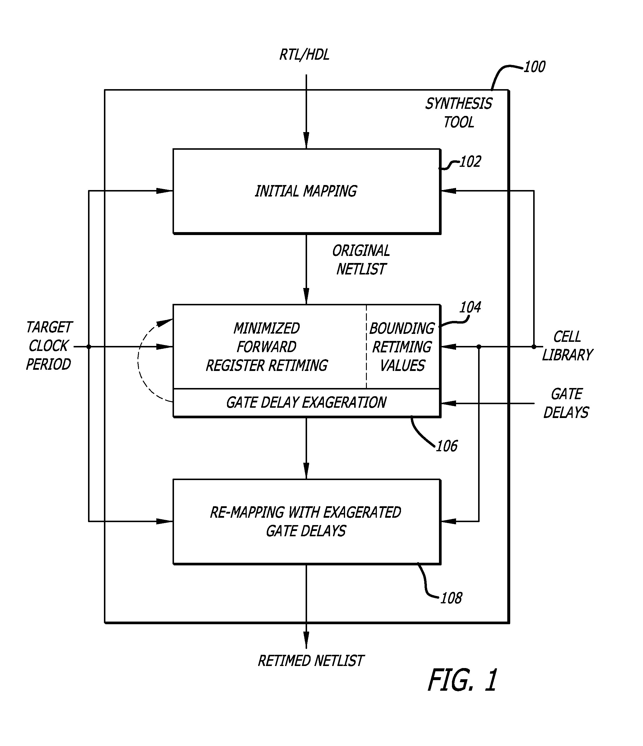
FIELD[0001]The embodiments of the invention relate generally to retiming integrated circuit netlists during logic synthesis. More particularly, the embodiments of the invention relate to constraint based retiming with boundaries to maximize forward movement of flip-flops.BACKGROUND[0002]During logic synthesis, logic cells from a cell library are mapped into a netlist to begin the physical design process of an integrated circuit. In order that logical computations can be made within a given clock period, logic gates in a data path are often separated by D-type flip flops during the logic synthesis process. Oftentimes the logic gates are conservatively placed between D-type flip flops such that the timing delays can easily beat out the given clock period. However, this leads to overly conservative designs that are not area efficient. Retiming the logic gates in a data path by moving the flip flops forward or backward to eliminate one or more flip flops can conserve area in an integrat...

Claims


Application Information

Patent Timeline
IPC IPC(8): G06F17/50G06F9/45
CPCG06F17/5031G06F2217/84G06F30/3312G06F2119/12
Inventor ALBRECHT, CHRISTOPHRICHTER, SASCHA
Owner CADENCE DESIGN SYST INC
Learn More