Electromagnetic switch equipped with built-in electronic control circuit

a technology of electronic control circuit and electromagnetic switch, which is applied in the direction of motors, machines/engines, and magnetic bodies, etc., can solve the problems of increasing the volume and manufacturing cost of electromagnetic switch, reducing the ease of installation of electronic control circuit, and reducing the electric insulation between. , to achieve the effect of reducing the const, reducing the size of the switch case, and increasing the outer diameter of the switch cas

Inactive Publication Date: 2011-05-24
DENSO CORP
View PDF15 Cites 32 Cited by
  • Summary
  • Abstract
  • Description
  • Claims
  • Application Information

AI Technical Summary

Benefits of technology

[0011]It is another object of the invention to provide an improved structure of an electromagnetic switch designed to install an electronic control circuit within an electromagnetic switch without being exposed to conductive dusts arising from the wear of contacts and interfering with a path along which a movable contact is to move.
[0018]The electromagnetic switch further comprise a chamber defined between an end of the resinous bobbin and the circuit board of the electronic control circuit. The chamber is filled with a resin material which is lower in thermal conductivity than the bobbin. This reduces the heat which is produced by energization of the exciting coil and transmitted to the electronic control circuit, which permits the ability of the electronic control circuit to withstand a rise in temperature of the exciting coil.

Problems solved by technology

The electronic control circuit is, therefore, exposed to the dusts, so that the dusts are deposited on the surface of the electronic control circuit, which may result in a decrease in electric insulation between electric devices mounted on the electronic control circuit and short-circuits therebetween.
Therefore, the installation of the electronic control circuit within the contact cover requires a circuit board and conductive leads connecting with the circuit board to be blocked or shielded by an electric insulator, which will result in increases in volume and manufacturing cost of the electromagnetic switch.
It is also necessary to place the electronic control circuit within the contact cover away from a path along which the movable contact is to move in an axial direction of the contact cover, which may result in complex configuration of the circuit board and complex layout of the electric devices on the circuit board, thus leading to a decrease in ease of installation of the electronic control circuit.

Method used


Image

  • Electromagnetic switch equipped with built-in electronic control circuit
  • Electromagnetic switch equipped with built-in electronic control circuit
  • Electromagnetic switch equipped with built-in electronic control circuit

Examples


Embodiment Construction

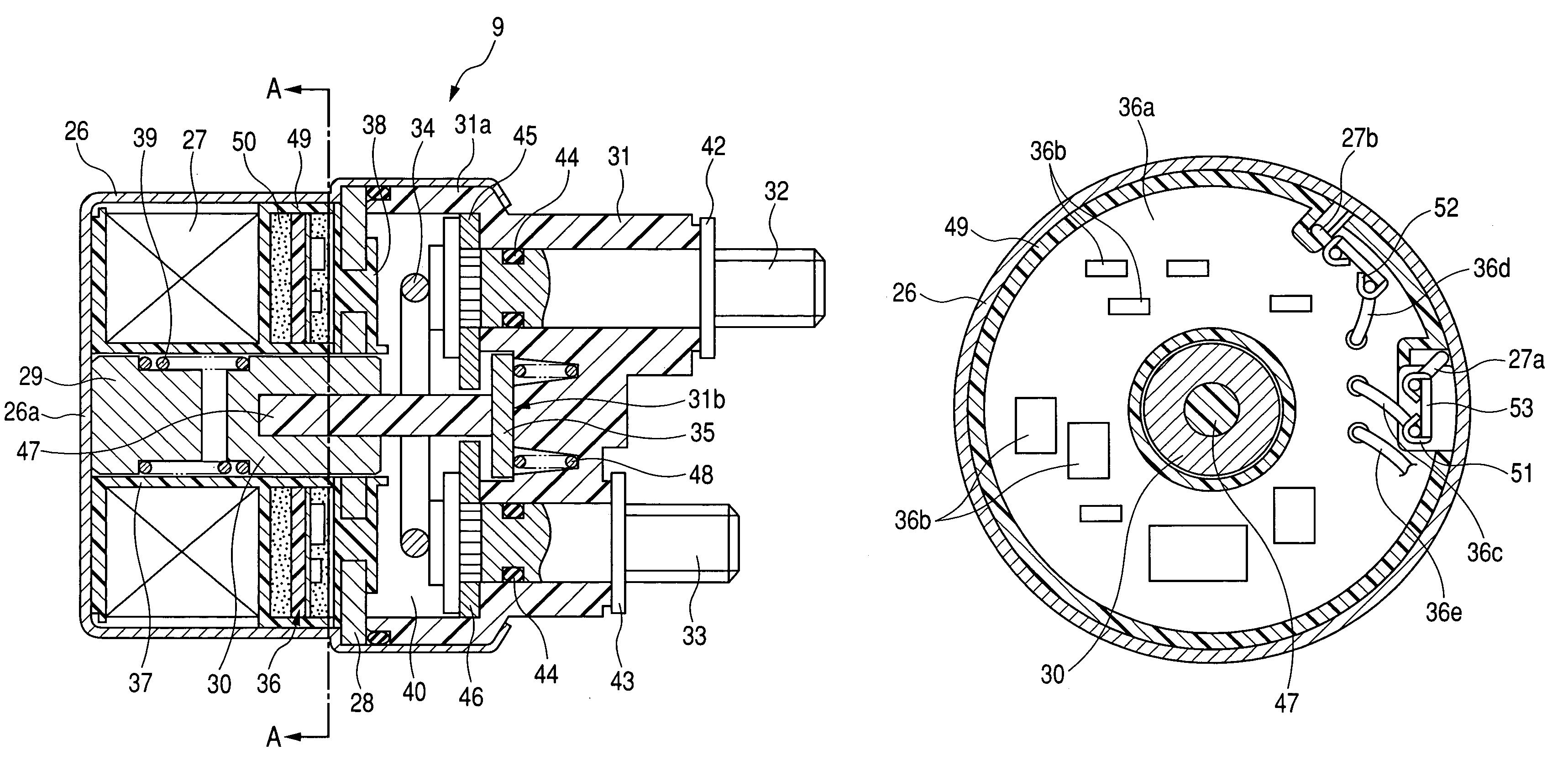
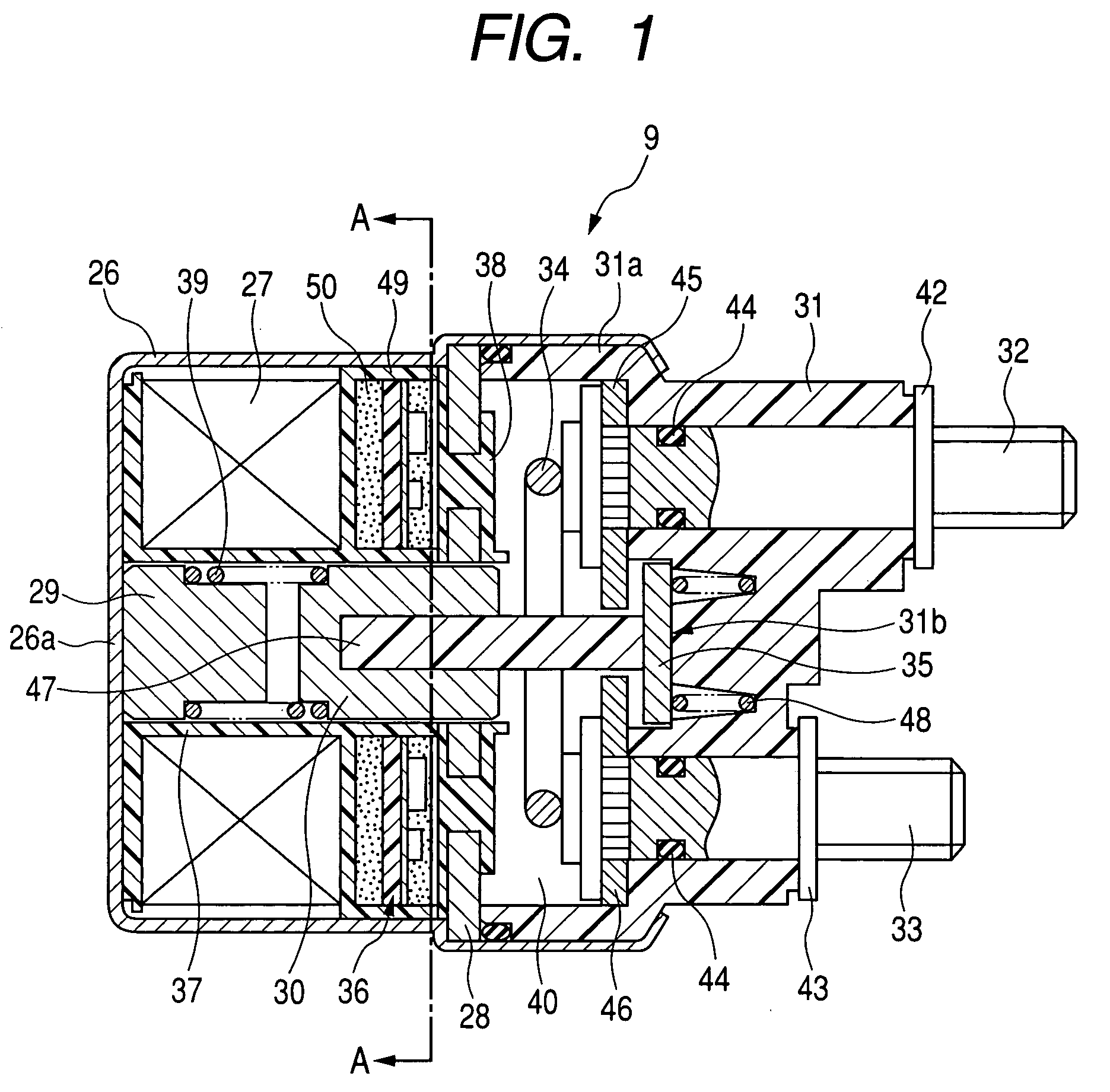
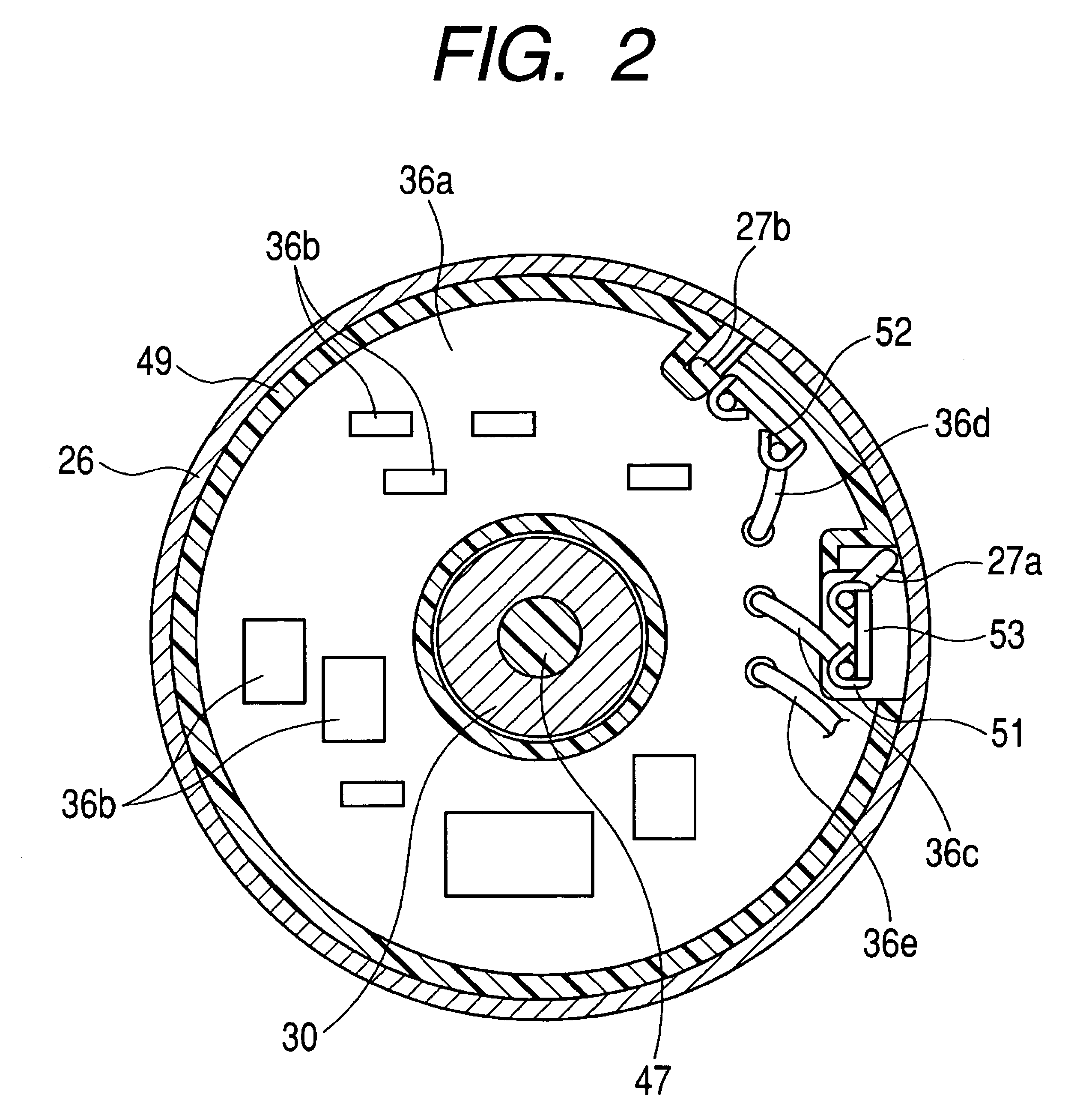
[0026]Referring to the drawings, wherein like reference numbers refer to like parts in several views, particularly to FIG. 1, there is shown an electromagnetic switch 9 which is installed, as an example, in an automotive engine starter 1 illustrated in FIG. 3. FIG. 1 is a longitudinal sectional view of the electromagnetic switch 9. FIG. 2 is a traverse sectional view, as taken along the line A-A of FIG. 1. FIG. 3 is a plane view of the starter 1. FIG. 4 is a diagram which shows an electric circuit for the starter 1.

[0027]The starter 1 is, as illustrated in FIGS. 3 and 4, equipped with a housing 2, an electric motor 4, a pinion gear 6, a shift lever 7, a main electromagnetic switch 8, and the electromagnetic switch 9. The electromagnetic switch 9 is used as an auxiliary switch and will be referred to as a sub-electromagnetic switch below.

[0028]The housing 2 is to be secured to an automotive internal combustion engine (not shown). The electric motor 4 is joined to the housing 2 using ...


PUM

PropertyMeasurementUnit
electromagneticaaaaaaaaaa
thermal conductivityaaaaaaaaaa
sizeaaaaaaaaaa

Abstract

An electromagnetic switch is provided which is equipped with a built-in electronic control circuit working to control energization of an exciting coil. The electronic control circuit is disposed within a chamber defined by a magnetic plate to be separate from a contact chamber. In other words, the electronic control circuit is disposed between the magnetic plate and the exciting coil, thereby avoiding the adhesion of conductive dusts, as arising from the wear of contacts, to the surface of the electronic control circuit. This results in decreases in electric insulation and short-circuit of the electronic control circuit and also eliminates the need for additional special parts to electrically insulate and shield the electronic control circuit, thus permitting the electromagnetic switch to be reduced in size and produced at a decreased const.

Description

CROSS REFERENCE TO RELATED DOCUMENT[0001]The present application claims the benefit of Japanese Patent Application No. 2008-204189 filed on Aug. 7, 2008, the disclosure of which is incorporated herein by reference.BACKGROUND OF THE INVENTION[0002]1. Technical Field of the Invention[0003]The present invention relates generally to an electromagnetic switch which is equipped with a built-in electronic control circuit and to be installed in a starter to start an automotive engine.[0004]2. Background Art[0005]Japanese Patent First Publication No. 9-105372 discloses an electromagnetic switch equipped with a built-in electronic control circuit to control energization of an exciting coil.[0006]The electromagnetic switch is designed to use attraction, as produced by an electromagnet developed by the exciting coil, to open or close main contacts of a motor circuit. The electronic control circuit is disposed inside a contact cover in which the main contacts are installed. This structure is sma...

Claims


Application Information

Patent Timeline
Patent Type & Authority Patents(United States)
IPC IPC(8): H01H67/02H01F7/18H01F7/08H01H9/00H01F7/00
CPCH01H50/30H01H51/06F02N15/067F02N11/00F02N11/087F02D2400/18F02N11/08H01H50/14
Inventor NIIMI, MASAMISUZUKI, YOSHIAKI
Owner DENSO CORP
Why Eureka
Try Eureka