Error compensation in phase shifting interferometry

a phase shifting and error compensation technology, applied in the field of phase shifting interferometry, can solve the problems of distorted interference signal, errors in phase determination, and various signal distortions of sinusoidal psi, and achieve the effects of improving interferometer design, improving performance, and being convenient to implemen

Active Publication Date: 2011-05-24
ZYGO CORPORATION
View PDF17 Cites 18 Cited by
  • Summary
  • Abstract
  • Description
  • Claims
  • Application Information

AI Technical Summary

Benefits of technology

[0011]Sinusoidal PSI can beneficially relax requirements on the phase-shifting mechanism in an interferometer and can be easier to implement compared to linear PSI. Sinusoidal PSI can also facilitate improvements in interferometer design based on high-speed, continuous data averaging, which is beneficial for increased performance in the presence of electronic, optical and environmental noise.
[0016]As a further improvement for sinusoidal PSI, data can be acquired and averaged using a varying phase offset. Then, residual errors that are periodic with phase are averaged to further reduce errors of all kinds, including those related to multiple round-trip reflections within the Fizeau cavity.

Problems solved by technology

However, sinusoidal PSI can be subject to various signal distortions.
Such signal distortions result from the coherent superposition of light being reflected multiple times between the reference surface and the test surface and can cause errors when determining the phase difference between the reference light and the test light.
For example, PSI algorithms can be design for interferometer geometries for which there are multiple or spurious reflections in addition to the expected reflections from the object and reference surfaces, resulting in a distorted interference signal.

Method used


Image

  • Error compensation in phase shifting interferometry
  • Error compensation in phase shifting interferometry
  • Error compensation in phase shifting interferometry

Examples


Embodiment Construction

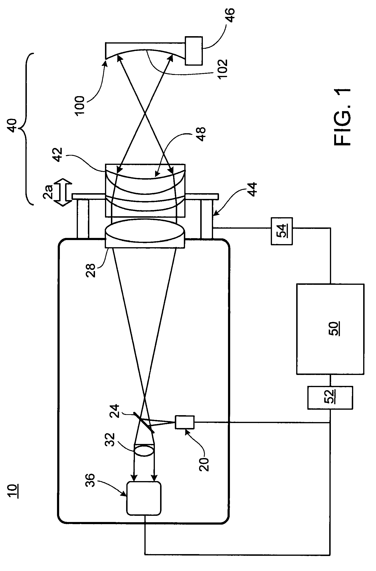
[0087]In FIG. 1, a schematic diagram of a phase-shifting interferometric system 10 is shown. Phase-shifting interferometric system 10 is adapted to measure the profile of a test surface 102 of a measurement object 100. Phase-shifting interferometric system 10 includes a light source 20 (e.g., a laser), a beam splitter 24, a collimating optic 28 for collimating light emitted from the light source, a Fizeau cavity 40 (e.g., a spherical cavity), a charge coupled device (CCD) camera 36, and an imaging optic 32 for imaging light exiting Fizeau cavity 40 onto camera 36. Phase-shifting interferometric system 10 includes further a controller 50 (e.g., a computer) and a frame grabber 52 for reading images detected by CCD camera 36.

[0088]Spherical-cavity Fizeau cavity 40 includes reference optics 42 mounted on a translatable stage 44. Translatable stage 44 is in communication with controller 50 through a driver 54. Spherical-cavity Fizeau cavity 40 includes further a mount 46 for positioning ...


PUM


Abstract

In certain aspects, disclosed methods include combining reference light reflected from a reference surface with test light reflected from a test surface to form combined light, the test and reference light being derived from a common source, sinusoidally varying a phase between the test light and reference light, where the sinusoidal phase variation has an amplitude u, recording at least one interference signal related to changes in an intensity of the combined light in response to the sinusoidal variation of the phase, determining information related to the phase using a phase shifting algorithm that has a sensitivity that varies as a function of the sinusoidal phase shift amplitude, where the sensitivity of the algorithm at 2 u is 10% or less of the sensitivity of the algorithm at u.

Description

TECHNICAL FIELD[0001]This disclosure relates to phase-shifting interferometry, and, in particular, to phase shifting interferometry using Fizeau-cavities.BACKGROUND[0002]Interferometric optical techniques are widely used to measure optical thickness, flatness, and other geometric and refractive index properties of precision optical components such as glass substrates used in lithographic photomasks.[0003]For example, one can use an interferometer to combine a test wavefront reflected from a test surface with a reference wavefront reflected from a reference surface to form an optical interference pattern. Spatial variations in the intensity profile of the optical interference pattern correspond to phase differences between the combined test and reference wavefronts caused by, for example, variations in the profile of the test surface relative to the reference surface.[0004]Phase-shifting interferometry (PSI) can be used to accurately determine the phase differences and the correspond...

Claims


Application Information

Patent Timeline
Patent Type & Authority Patents(United States)
IPC IPC(8): G01B9/02
CPCG01B9/02004G01B9/0201G01B9/02059G01B9/02069G01B9/02083G01B9/02057G01B2290/35
Inventor DE GROOT, PETER
Owner ZYGO CORPORATION
Why Eureka
Try Eureka