Solar distillation device

a distillation device and solar energy technology, applied in the direction of refrigerating components, drying solid materials, drying using combination processes, etc., can solve the problems of mineral (scale) buildup in the evaporation tube, device sensitivity, and limited effectiveness

Active Publication Date: 2011-06-07
MCCLURE MILES
View PDF33 Cites 46 Cited by
  • Summary
  • Abstract
  • Description
  • Claims
  • Application Information

AI Technical Summary

Benefits of technology

[0025]Other embodiments of the present invention provide a machine for evaporating liquids, comprising a substantially vertical, tubular evaporation reactor adapted to provide a liquid concentrate region below a feed liquid region, a base located at a lower end of said evaporation reactor, a cap structure located at an upper end of said evaporation reactor, at least one feed liquid opening in said base located within the area circumscribed by said evaporation reactor and at least one tubular extension fit to each of said at least one feed liquid opening on an upper surface of said base, wherein said extension terminates in said feed liquid region, and whereby such arrangement allows the feed liquid to remain substantially separated from the liquid concentrate, at least one concentrate opening in said base located within the area circumscribed by said evaporation reactor, each said concentrate opening adapted to act as a passageway for liquid concentrate to exit said evaporation reactor, at least one vapor opening in said cap structure, in said base, or both and at least one vapor conduit hydraulically connected to said opening, and at least one tension member that connects said base to said cap structure and which is adapted to compress said evaporation reactor between said base and said cap structure, thereby creating substantially watertight seals between said base, said evaporation reactor, and said cap structure.

Problems solved by technology

In fact, much of the developing world's population lives where potable water is extremely rare.
Because these devices rely on direct solar heating, their effectiveness is limited by the size of the device.
Unfortunately, these devices are susceptible to mineral (scale) buildup in the evaporation tubes.
This can be partially overcome by the use of a closed heating circuit with an engineered working fluid, but this solution adds another level of complexity and additional heat transfer loss between loops.
This design shows one advantage of a vertical reactor arrangement, that of compact size, but it also shows the difficulty in supporting the reactor column at sizes larger than desktop units.
In addition, the device uses complex valves to maintain suitable fluid levels and temperatures within the boiler and distilling tower.
Providing a cost-effective and workable method to separate the raw feed liquid from the concentrated liquid left behind after the vapor has been driven off is a problem common to all previous designs.
Batch mode operation is one method, but that solution eliminates continuous production and potentially wastes part of the daily sun cycle.

Method used


Image

  • Solar distillation device
  • Solar distillation device
  • Solar distillation device

Examples


example 1

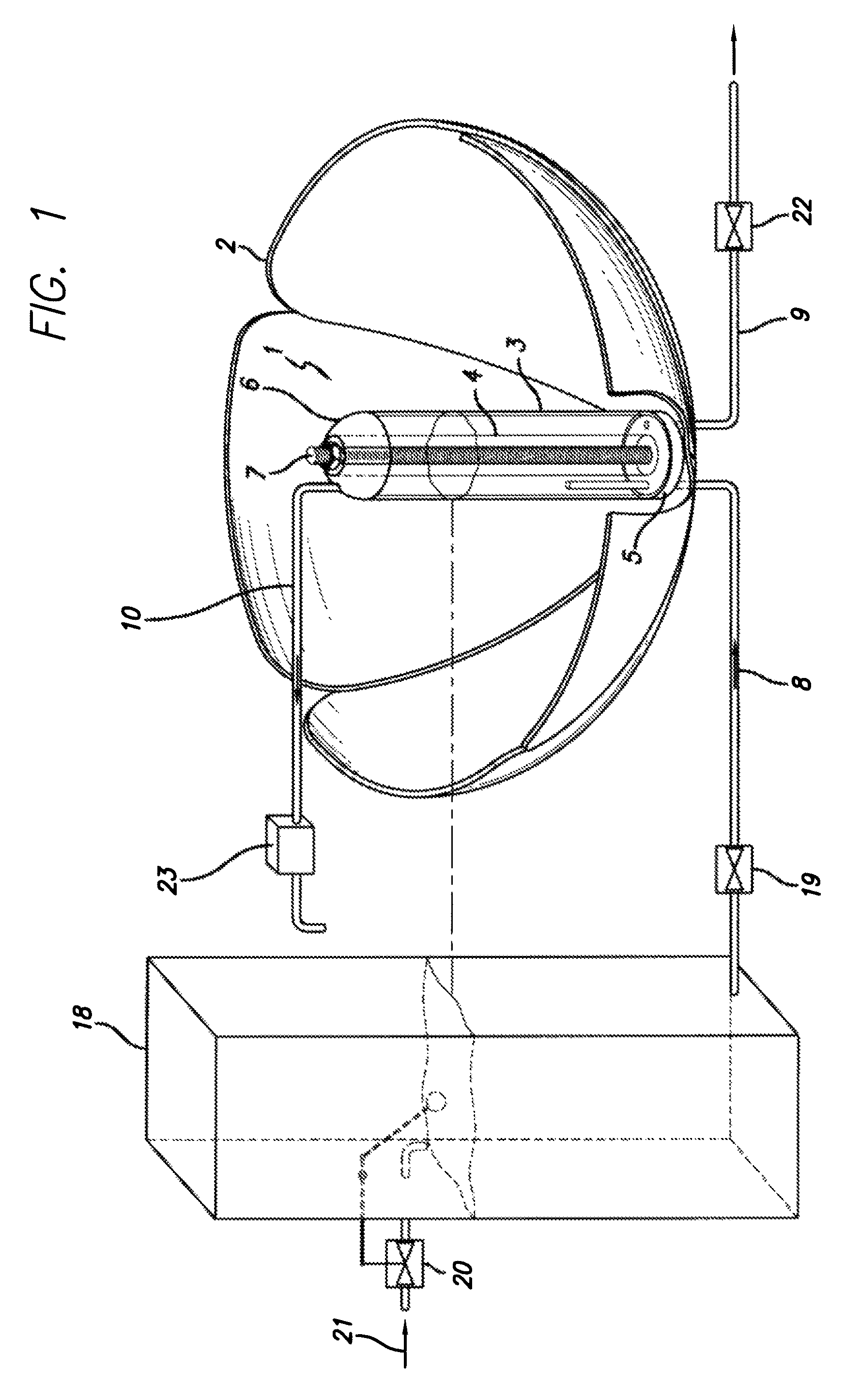
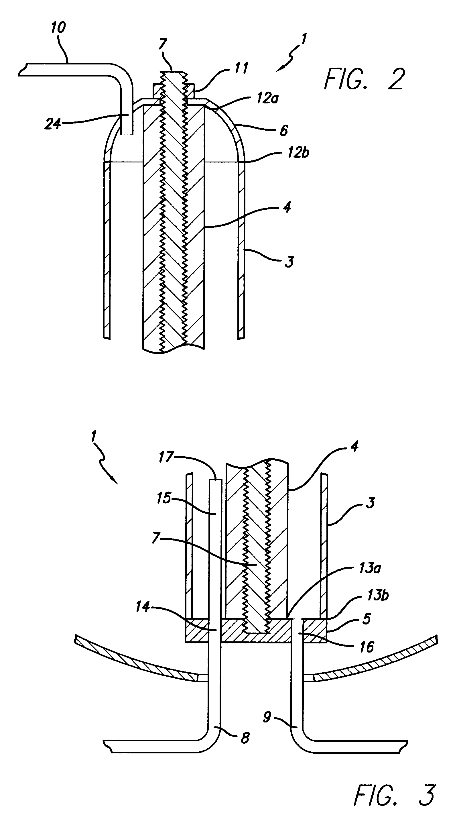
[0056]In a first exemplary embodiment, as shown in FIG. 1, the solar distillation device consists of evaporation reactor 1 centered in parabolic reflective dish 2, feed tank 18, condenser 23, and various connecting pipes or conduits described further below. The components of evaporation reactor 1 include outer cylinder 3, inner cylinder 4 located concentrically to outer cylinder 3, base 5, cap structure 6, and threaded rod 7. Outer cylinder 3 may be constructed of thin-walled glass. Inner cylinder 4 may also be constructed of glass, and in this embodiment is thicker walled. In various embodiments, the outer cylinder's wall thickness could be three-eighths (⅜) of an inch, and the outside diameter could be twelve (12) inches. The inner cylinder's wall thickness could be three (3) inches, and the outside diameter could be eight (8) inches. The cylinders could be approximately seven (7) feet tall in such an embodiment.

[0057]The annular space between outer cylinder 3 and inner cylinder 4...

example 2

[0067]FIG. 4 shows an example of the solar distillation device using the same basic concept of the evaporation reactor, but utilizing auxiliary equipment such as a moving reflector 40 with a drive mechanism 41 used to drive the reflector and track the sun's path across the sky. In FIG. 4, the concentrate valve 42 is automated. Based on operating data, an optimum concentrate flow can be generated by routine experimentation, and concentrate valve 42 can be modulated automatically in accordance with the contaminant concentration. Instrument 43 is used to measure the concentrate contaminate level through resistance, density, particle count, or other methodology as readily appreciated by someone skilled in the art.

[0068]Additionally, FIG. 4 shows automated feed valve 44, whereby the liquid level in reactor 45 is maintained by modulating feed valve 44, such modulations being based on level controller 46 output. Level controller 46 is any suitable instrument that monitors liquid level base...

example 3

[0069]FIG. 5 shows an embodiment utilizing a glass outer cylinder that includes metal wire 51 embedded within or affixed to the glass similar to shatterproof or security glass. The wire embedded in the outside cylinder can be arranged to act as an electric heating element to maintaining the water column temperature overnight, during overcast periods, or at other periods when auxiliary heating is advantageous.


PUM

PropertyMeasurementUnit
diameteraaaaaaaaaa
diameteraaaaaaaaaa
thicknessaaaaaaaaaa

Abstract

A solar distillation apparatus utilizing a substantially vertical reactor assembly is disclosed. The reactor includes a tubular outer shell, a base, a cap, and a central tension member. The annular space between the outer tube and the central tension member forms the reactor chamber. Seawater or other feed liquid enters the reactor chamber through the base plate. Reflected or direct solar energy heats the feed liquid, generating low pressure vapor. The vapor exits the reactor through the cap structure or the base. The concentrate left behind settles by gravity to the bottom region of the reactor's liquid column. Extension tubes on the feed openings allow feed liquid to enter the liquid column above the concentrate layer and avoid excessive mixing of the feed liquid and the concentrate. The concentrate exits the reactor through one or more openings in the base.

Description

BACKGROUND[0001]1. Field of the Invention[0002]This invention relates generally to the field of solar energy and systems, particularly to distillation of liquids by utilizing solar radiation.[0003]2. Discussion of Prior Art[0004]All publications herein are incorporated by reference to the same extent as if each individual publication or patent application was specifically and individually indicated to be incorporated by reference. The following description includes information that may be useful in understanding the present invention. It is not an admission that any of the information provided herein is prior art or relevant to the presently claimed invention, or that any publication specifically or implicitly referenced is prior art.[0005]As the cost of fossil fuels increases and the scarcity of potable water becomes more acute, the need for alternative methods of freshwater production becomes greater each year. In fact, much of the developing world's population lives where potable...

Claims


Application Information

Patent Timeline
Patent Type & Authority Patents(United States)
IPC IPC(8): B01D1/06B01D3/04C02F1/14
CPCB01D1/0082B01D1/0035Y10S203/01Y10S203/11Y10S203/08Y10S159/903Y02E10/44Y02A20/142Y02A20/212F24S23/71F24S20/20F24S10/45Y02A20/124Y02E10/40
Inventor MCCLURE, MILES
Owner MCCLURE MILES
Why Eureka
Try Eureka