

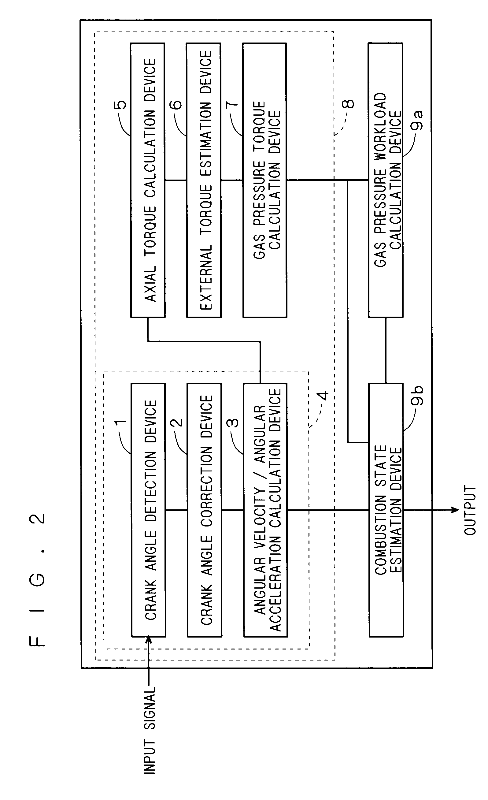
Angular velocity/angular acceleration calculator, torque estimator, and combustion state estimator
a technology of angular acceleration and calculator, which is applied in the direction of instruments, electrical control, force/torque/work measurement apparatus, etc., can solve the problems of durability and cost, the method of japanese patent application laid-open no. 2005, and the inability to calculate an angular acceleration. to achieve accurate estimation of the combustion sta
- Summary
- Abstract
- Description
- Claims
- Application Information
AI Technical Summary
Benefits of technology
Problems solved by technology
Method used
Image

Examples
embodiment
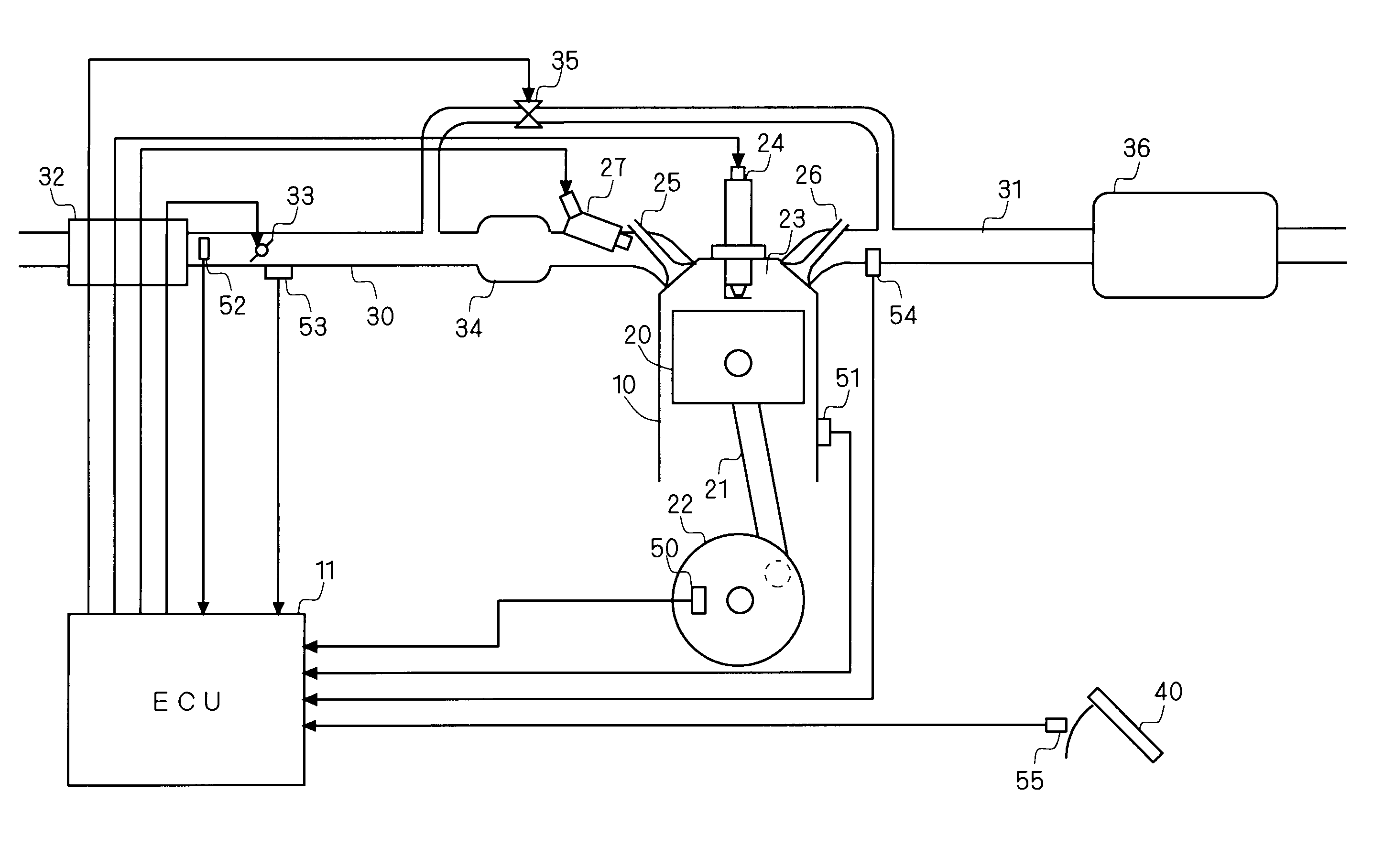
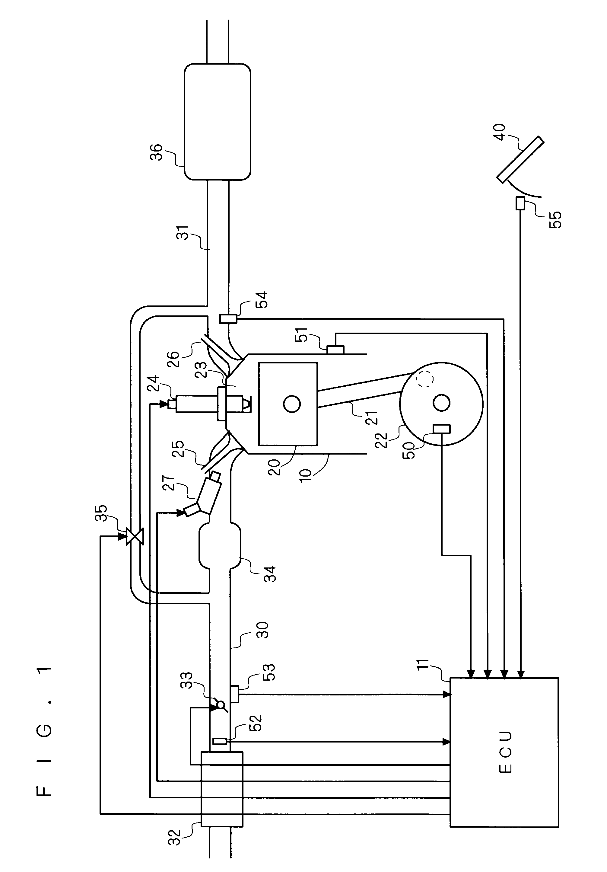
[0022]FIG. 1 is a schematic diagram of an internal combustion engine that includes a combustion state estimator according to the present embodiment. The internal combustion engine shown in FIG. 1 exemplifies a four-stroke straight four-cylinder engine. FIG. 1 shows an engine 10 that has pistons 20 respectively provided in the cylinders, and combustion chambers 23 respectively disposed above the pistons 20.
[0023]The engine 10 is connected to an intake path 30 and an exhaust path 31. Intake air passes through an air filter 32 that is provided at an upstream end of the intake path 30, and enters a surge tank 34 via an airflow sensor 52 and a throttle valve 33. Disposed in the vicinity of the throttle valve 33 is a throttle sensor 53 that detects the amount of throttle opening. The air having entered the surge tank 34 is taken into the combustion chambers 23 of the respective cylinders via intake valves 25 that are provided at a downstream end of the intake path 30. Disposed on the down...
PUM
 Abstract
Description
Claims
Application Information