

Multiple image camera and lens system
a camera and lens technology, applied in the field of imaging systems, can solve the problems of vignetting (an unwanted effect), spectral dispersion error, and aberration in the multiple images of the camera, and achieve the effect of reducing the number of images
- Summary
- Abstract
- Description
- Claims
- Application Information
AI Technical Summary
Benefits of technology
Problems solved by technology
Method used
Image

Examples
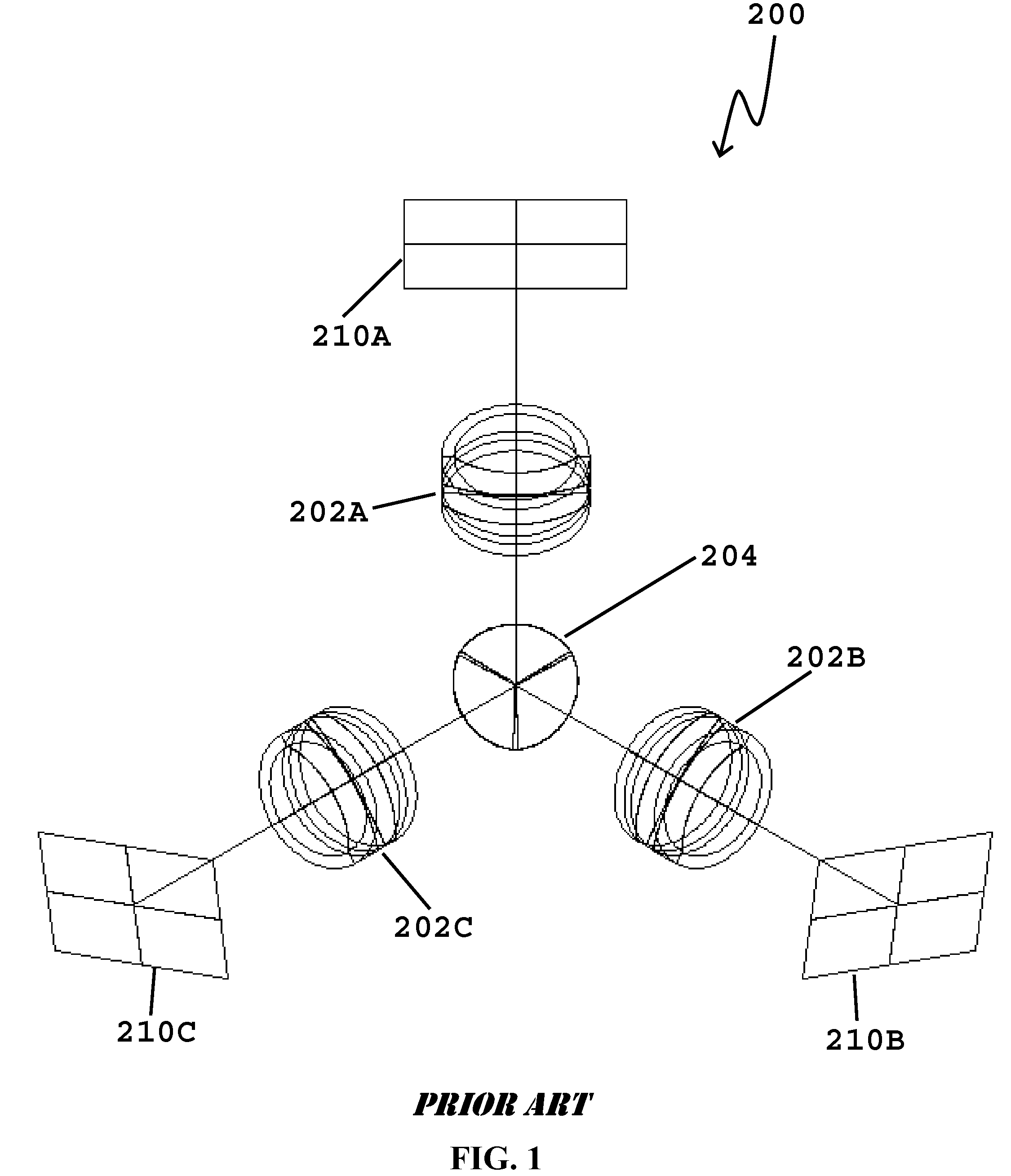
embodiment 100
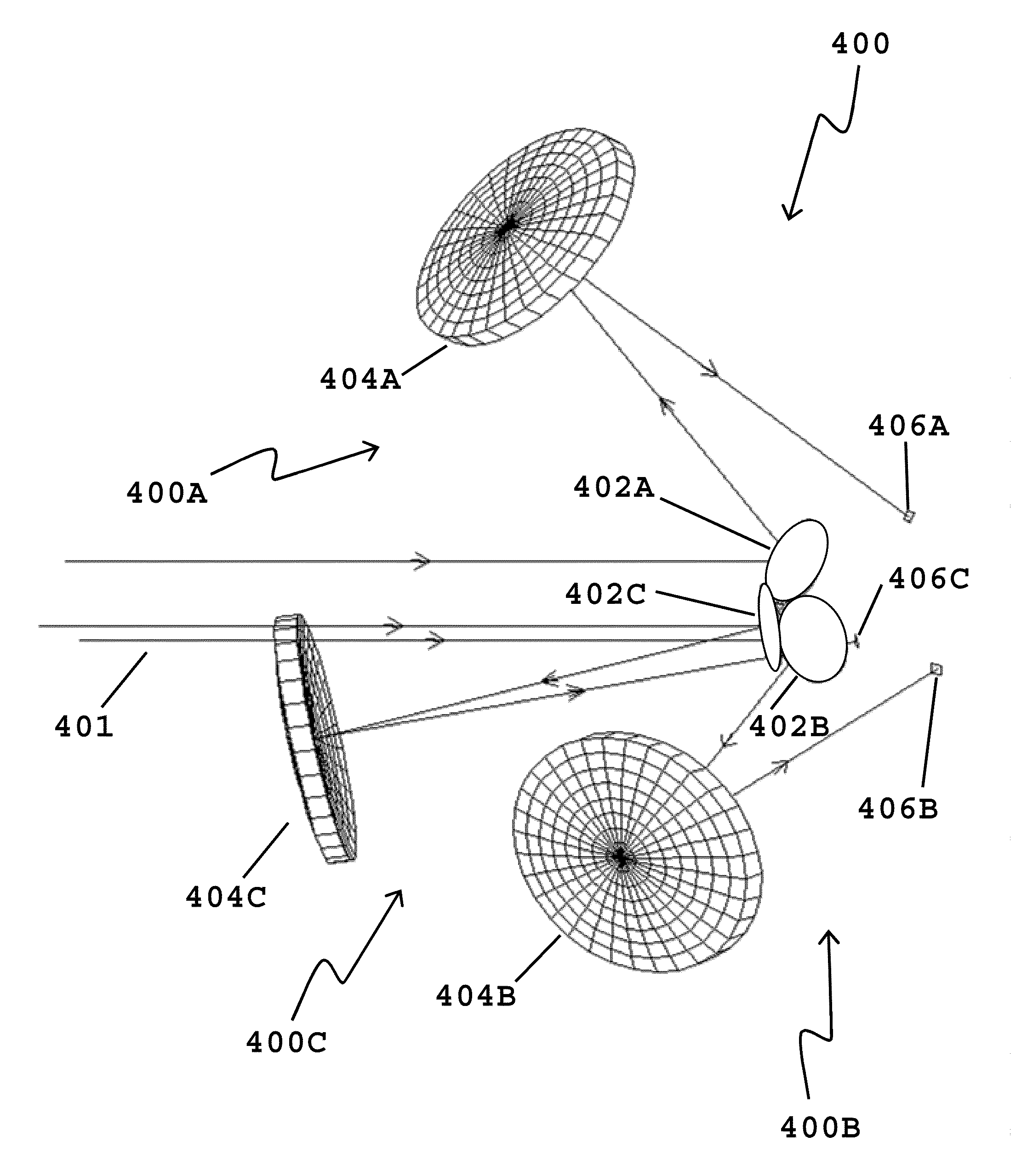
FIGS. 3, 4, and 5 respectively depict a perspective view, a side view, and an end view, respectively of an embodiment of the present invention 100. The components of this first preferred embodiment 100 include three substantially identical imaging lens systems 102A, 102B, and 102C, positioned such that the entrance pupils for these three lenses substantially coincide with the centers of three elliptical-shaped mirrors 104A, 104B, and 104C, respectively. Mirrors 104A, 104B, and 104C are preferably small and flat. Optical radiation 106 from a distant object reflects from the three flat mirrors 104A, 104B, and 104C (and is thus spatially split) into three different directions 108A, 108B, and 108C and is thereafter caused by the three lenses 102A, 102B, and 102C to form three substantially identical images on three detector planes 110A, 110B, and 110C, respectively. Although the shape of each of mirrors 104A, 104B, and 104C may be elliptical (or another shape), the actual cross-section ...
embodiment 400
In diffraction limited embodiment 400, optical filter 440A may optionally be disposed between the mirror 402A and mirror 404A. The exact location of optical filter 440A is not important as long as it is located so that it acts only on the light that is used in the single arm 400A to form an image on detector 406A and so that it does not act on light that is used to form images on the other detectors 406B and 406C. For example, the optical filter 440A may alternatively be placed in a location that is substantially similar to the location of mirror 402A.
An example of this embodiment in accordance with FIGS. 12-15 (without optional optical filter 440A) was simulated, wherein center 424A of mirror 402A was displaced upward from the axis of symmetry 422 by a distance of 11.547 mm (in a direction perpendicular to axis of symmetry 422), which corresponds to a mirror 402A with a minor-axis diameter of 20.0 mm. The normal to the elliptical mirror face, at its vertex, was tilted upward at an ...
PUM
 Abstract
Description
Claims
Application Information