Membrane based concentrators

a membrane-based, concentrator technology, applied in water/sewage treatment by ion exchange, water/sewage treatment by osmosis/dialysis, drying using combination processes, etc., can solve problems such as chromatographic equipment or inline, interference with quantification of other anions, and inability to detect trace ions in the presence of matrix ions

Active Publication Date: 2011-06-21
BOARD OF RGT THE UNIV OF TEXAS SYST
View PDF29 Cites 15 Cited by
  • Summary
  • Abstract
  • Description
  • Claims
  • Application Information

AI Technical Summary

Problems solved by technology

Depending on the concentration, the presence of the carbonate peak may interfere with quantitation of other anions such as sulfate.
When pursuing trace analysis with environmental samples such as drinking water the detection of trace ions in the presence of matrix ions is an issue.
These are all typically offline methods that are implemented using bench top equipment and as such are not amenable for use with chromatographic equipment or inline chromatography.
These approaches do not preserve the separation and involve multiple steps and transfer processes that can potentially hinder the recovery and quantitation of analytes of interest.
The peak shapes are not preserved, and this method is not well suited for post analytical steps.
The above method was a pre injection sample pretreatment approach and suffered from the limitation of coping with possible contamination issues from the sample vials.

Method used


Image

  • Membrane based concentrators
  • Membrane based concentrators
  • Membrane based concentrators

Examples


example 1

Membrane Tube Based Concentrators

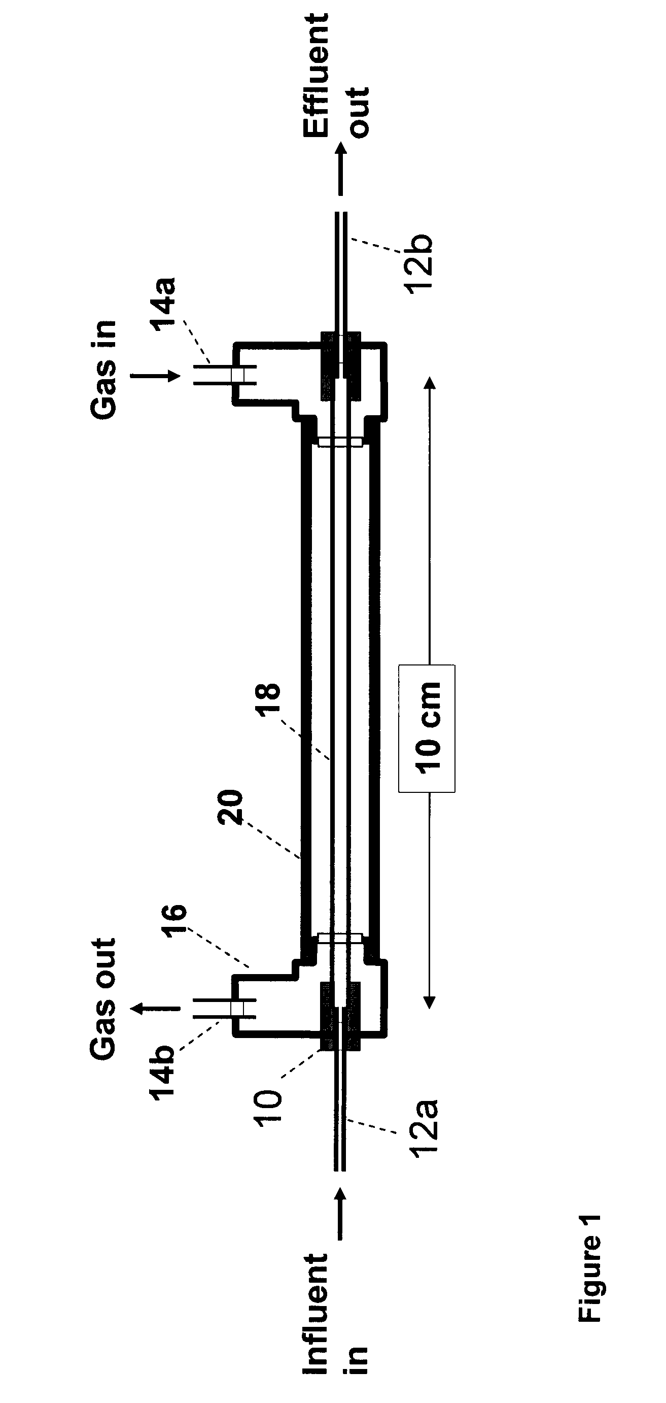
[0074]Initial studies on the performance of different membrane devices were carried out using 10 cm lengths of each membrane. FIG. 1 is a schematic of the tubular concentrator. The membrane tube was enclosed in a PTFE tube 20 (6.7 mm id, 7.7 mm od, 80 mm long, Zeus Industrial Products, Inc.). A polyvinyl chloride (PVC) pump tube 10 (190 μm id, 2 mm od, 5 mm long, Cole-Parmer Instrument Co.) was used as a butt-connector between the membrane tube and fused silica capillary 12a or 12b (250 μm i.d., 365 μm o.d., Polymicro Technologies). Arms of ¼″ id polypropylene tee 16 (Ark-Plas Products Inc.) was appropriately cut and connected to the PTFE tube for gas inlet / outlet connections. Thus, the tubular membrane 18 is mounted in coaxial external tube 20. The heated gas flows through the annular space therebetween to heat the solvent in the influent aqueous liquid solvent stream. The temperature was monitored with a resistance thermal detector sensor (RTD sens...

example 2

Procedure for Coating a Hydrophobic (Celgard) Membrane With a Hydrophilic (Nafion) Coating

[0083]A length of Celgard membrane was immersed in methanol (Mallinckrodt) and then immersed and withdrawn from a 5% Nafion solution (Aldrich), followed by drying for 12 hours. It was then immersed a second time in the Nation solution and the second coating allowed to dry 12 h before use. By placing a thin coating of hydrophilic layer on top of the porous Celgard membrane the tubing is transformed to a hydrophilic membrane.

example 3

Maze Concentrator

[0084]FIGS. 3A-3C schematically show a maze type concentrator in which the membrane tube is in a serpentine path. These devices were built with the Nafion® tubes with an active length of 62 cm. Before assembling the device, the Nafion tube was boiled in 1 M sulfuric acid for 5 min to completely regenerate the tube, and washed thoroughly with water and allowed to dry. The Nafion tube 18 was strung through 0.5 mm apertures in 35 PEEK posts 58 ( 1 / 36 in. dia.) that were affixed in recesses in a right angled serpentine maze 62a machined in aluminum block 62. The groove was 6.4 mm deep and 3.2 mm wide. The posts 58 served to prevent the Nafion tube 18 from touching the external walls or crimping at a turn. Both end of the membrane tube (ca. 1 mm) were inserted in a fluorinated ethylene propylene (FEP) tube (159 μm id, 254 μm od, 25 mm long) and 10-32 to 10-32 unions were used at each end for a leak-tight connection (12a and 12b). A resistance temperature detector (RTD) s...


PUM

PropertyMeasurementUnit
inner diameteraaaaaaaaaa
temperatureaaaaaaaaaa

Abstract

A sample concentrator for concentrating analytes in a solvent-containing liquid sample stream, including concentrator housing having a sample stream flow channel and a gas stream flow channel having an inlet and an outlet, a heater for gas in the gas stream conduit, and a hydrophilic ion exchange or non-ionic membrane barrier separating said gas stream flow channel and said sample stream flow channel. Solvent is evaporated from the liquid sample stream in said sample stream flow channel in or at the interface with said membrane, when the gas stream is at an elevated temperature. A regeneration step is used to regenerate the ion exchange membrane barrier.

Description

BACKGROUND OF THE INVENTION[0001]1. Field of Invention[0002]The present invention relates to a sample concentrator system. More particularly, the present invention relates to an online sample concentrator system based on solvent evaporation for use in a chromatography system.[0003]2. Description of the Related Art[0004]Preconcentration in a chromatography system, performed prior to detection of the analytes, typically is performed by concentrating the analytes in a column that is preferably selective to the analytes of interest and then subsequently eluting the trapped or concentrated species for further analysis. When analyte concentrations are too low to produce an adequate detector response a variety of solutions are implemented. Traditional solutions to this problem include prior sample workup to increase analyte concentration, large volume injection with or without preconcentration on a solid phase, adoption of a more sensitive detector, or a change to a more sensitive detectio...

Claims


Application Information

Patent Timeline
Patent Type & Authority Patents(United States)
IPC IPC(8): G01N30/02
CPCG01N1/4005G01N1/4022G01N30/08Y10T436/255G01N2001/4011G01N2001/4027G01N2030/146G01N30/96
Inventor DASGUPTA, PURNENDUTAKEUCHI, MASAKISRINIVASAN, KANNAN
Owner BOARD OF RGT THE UNIV OF TEXAS SYST
Why Eureka
Try Eureka