Spherical array laser source

a laser source and array technology, applied in the direction of laser details, laser optical resonator construction, semiconductor lasers, etc., can solve the problems of lossy fiber coupling of light into fibers, affecting the efficiency of laser sources and optical amplifiers, and reducing the efficiency of fiber coupled sources

Active Publication Date: 2011-06-21
THE BOEING CO
View PDF5 Cites 8 Cited by
  • Summary
  • Abstract
  • Description
  • Claims
  • Application Information

AI Technical Summary

Benefits of technology

[0006]Exemplary embodiments provide a laser source employing a reflecting spherical substrate and an array of emitters coincident with the spherical substrate and having a transverse extent greater than or equal to the extent of the fundamental cavity mode at the spherical substrate, referred to herein as a mode dimension. Each emitter has an emission axis of symmetry aligned with a radius of the spherical substrate. A single mode waveguide is aligned with the array at an optical coupling distance less than the radius of the spherical substrate. A reflector substantially coincident with an end of the waveguide combines with the reflecting spherical substrate to form a cavity.

Problems solved by technology

Arrays of semiconductor laser sources are difficult to couple into single mode waveguides efficiently therefore affecting the efficiency of laser sources and optical amplifiers.
These approaches typically result in lossy coupling of light into fibers, reducing the efficiency of the fiber coupled source.

Method used


Image

  • Spherical array laser source
  • Spherical array laser source
  • Spherical array laser source

Examples


first embodiment

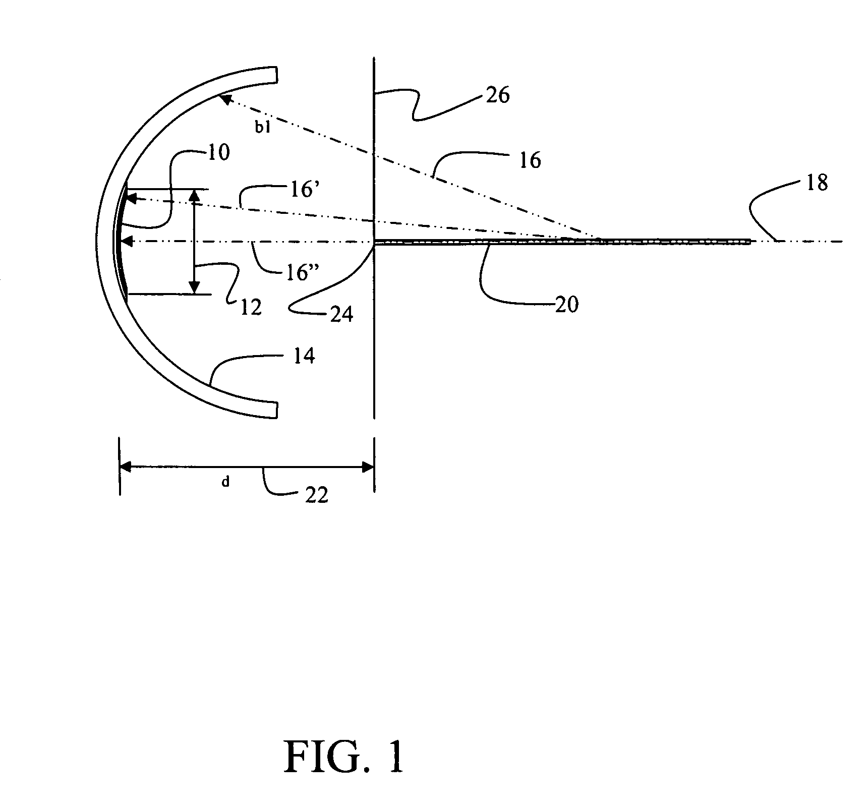
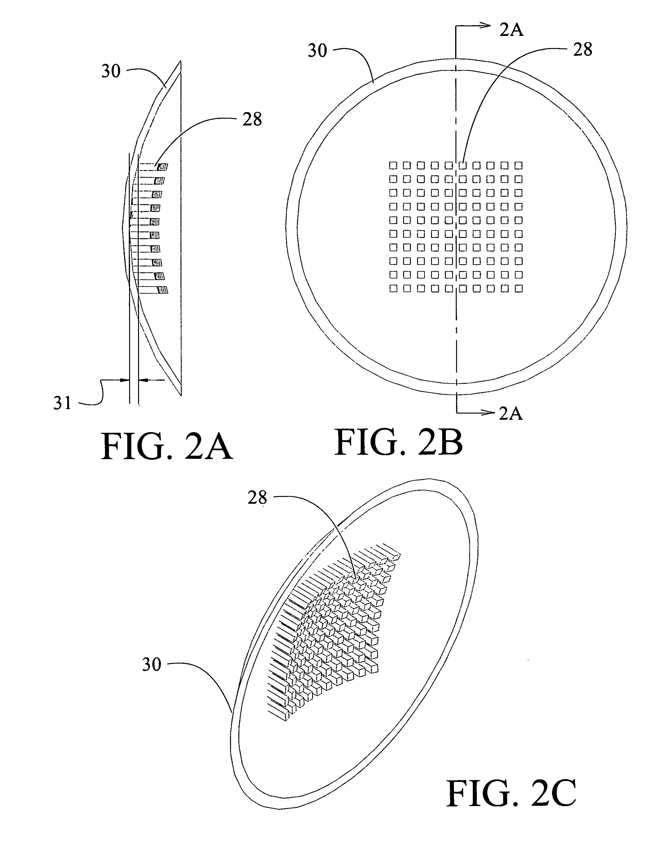
[0028]The embodiments disclosed herein provide spherical arrangement of the emission axes of an array of semiconductor optical emitters which are coupled with a partially transmitting reflector located near the center of curvature of the spherical geometry as will be described with respect to Table I subsequently. The transmitted optical field is coupled into a single mode waveguide or single mode fiber, such that the waveguide mode matches the cavity mode at the reflector. Referring to FIG. 1, an array of emitters 10 having a mode dimension 12 is mounted on a reflecting spherical substrate 14 having a radius 16. For the embodiment shown a circular array with a diameter greater than or equal to the mode dimension 12 is employed. Curvatures in FIG. 1 have been exaggerated. Exemplary emitters for a first embodiment are Vertical Cavity Surface-Emitting Lasers (VCSELS) described in greater detail subsequently. The spherical substrate is mounted and aligned so that the radius line 16′ of...

second embodiment

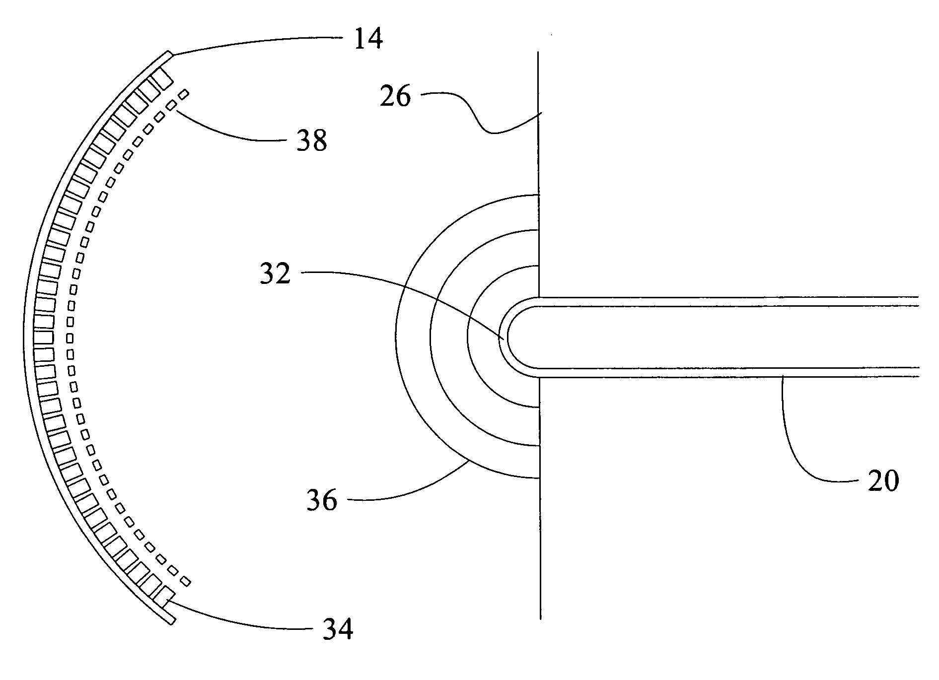
[0037]A second embodiment is shown in FIG. 3 which employs a hemispherical tip 32 on fiber 20 in conjunction with reflecting spherical substrate 14 as shown in the initial embodiment. The hemispherical tip is aligned with the center of VCSEL array 34 and employs a partially reflective coating. A wavefront 36 from the hemispherical tip is reflected to the spherical substrate. The transmittance / reflectance of the coating is predetermined based on desired cavity performance.

[0038]A lenslet array 38 may be employed in conjunction with the VCSEL array 34 to further control the light input and output for the VCSELs in the array. For the embodiment shown, the lenslet array incorporates an AR coating to maintain the two reflector cavity. The lenslet array may alternatively include a reflective coating to provide a three reflector laser cavity.

[0039]For the embodiment shown in FIG. 3, reflector 26 as disclosed in the initial embodiment is employed as a portion of the cavity. In alternative e...


PUM


Abstract

A laser cavity is provided by a reflecting spherical substrate with an array of emitters having a mode size. Each emitter has an axis aligned with a radius of the spherical substrate. A single mode waveguide is aligned with the array at an optical coupling distance less than the radius of the spherical substrate. A reflector substantially coincident with an end of the waveguide combines with the reflecting spherical substrate as a cavity.

Description

BACKGROUND INFORMATION[0001]1. Field[0002]Embodiments of the disclosure relate generally to the field of laser sources for fiber coupling and more particularly to embodiments for spherical mounting of an array of laser sources for coupling to single mode fiber with mode matching.[0003]2. Background[0004]Arrays of semiconductor laser sources are difficult to couple into single mode waveguides efficiently therefore affecting the efficiency of laser sources and optical amplifiers. Typical approaches to provide coupling employ planar arrays of emitters, and combine the output of the array by various methods that include splicing of single mode fibers from individual emitters, complex optical assemblies to focus planar array output onto the sides of fiber, optical arrangements coupling light into the ends of fibers. These approaches typically result in lossy coupling of light into fibers, reducing the efficiency of the fiber coupled source.[0005]It is therefore desirable to provide a sou...

Claims


Application Information

Patent Timeline
Patent Type & Authority Patents(United States)
IPC IPC(8): H01S5/00
CPCH01S5/423H01S5/4031H01S5/4062H01S3/08068H01S3/086H01S5/005H01S5/02284H01S5/14H01S5/405H01S5/4068H01S5/147H01S5/02326H01S5/02251
Inventor SAINT CLAIR, JONATHAN M.CHAN, ERIC YUEN-JUN
Owner THE BOEING CO
Why Eureka
Try Eureka