
Seafloor power station

a power station and seafloor technology, applied in the direction of machines/engines, nuclear elements, greenhouse gas reduction, etc., can solve the problems of large opposition, catastrophic peak temperatures in the fuel rods under such conditions, and substantial dredging for the construction of this cofferdam, so as to reduce the oxidation of components and eliminate the effect of convection cooling

Active Publication Date: 2011-07-12
HAYMAN III W Z ZACK
View PDF32 Cites 13 Cited by
  • Summary
  • Abstract
  • Description
  • Claims
  • Application Information

AI Technical Summary

Benefits of technology

[0012]The unmanned hull's interior would be in an effective vacuum during operation, to remove gasses from all components, including the condensers, and to provide the initial sealing of the hatch cover. Several beneficial effects occur from placing the interior in a vacuum: (1) air is excluded from the steam system; (2) the vacuum eliminates convection cooling of components, and; (3) the vacuum minimizes oxidation of components, electrical arcing and fire hazards. The hull would be maintained in a vacuum by hoses leading to vacuum tanks at the facility; these hoses also serve as conduits for the control circuits.

Problems solved by technology

Offshore Power Systems, a joint venture between Westinghouse and Newport News Shipbuilding, developed, but did not build a barge mounted nuclear powerplant for shipyard construction and subsequent mooring within a cofferdam.
Construction of this cofferdam would have required substantial dredging of the continental shelf and was widely opposed by local, environmental, fishing and shipping interests.
Peak temperatures in the fuel rods under such conditions would be disastrous.
Thus the limitations apparent in the prior proposals require further evolution if these offshore sites are to be utilized.

Method used


Image

  • Seafloor power station
  • Seafloor power station
  • Seafloor power station

Examples


Embodiment Construction

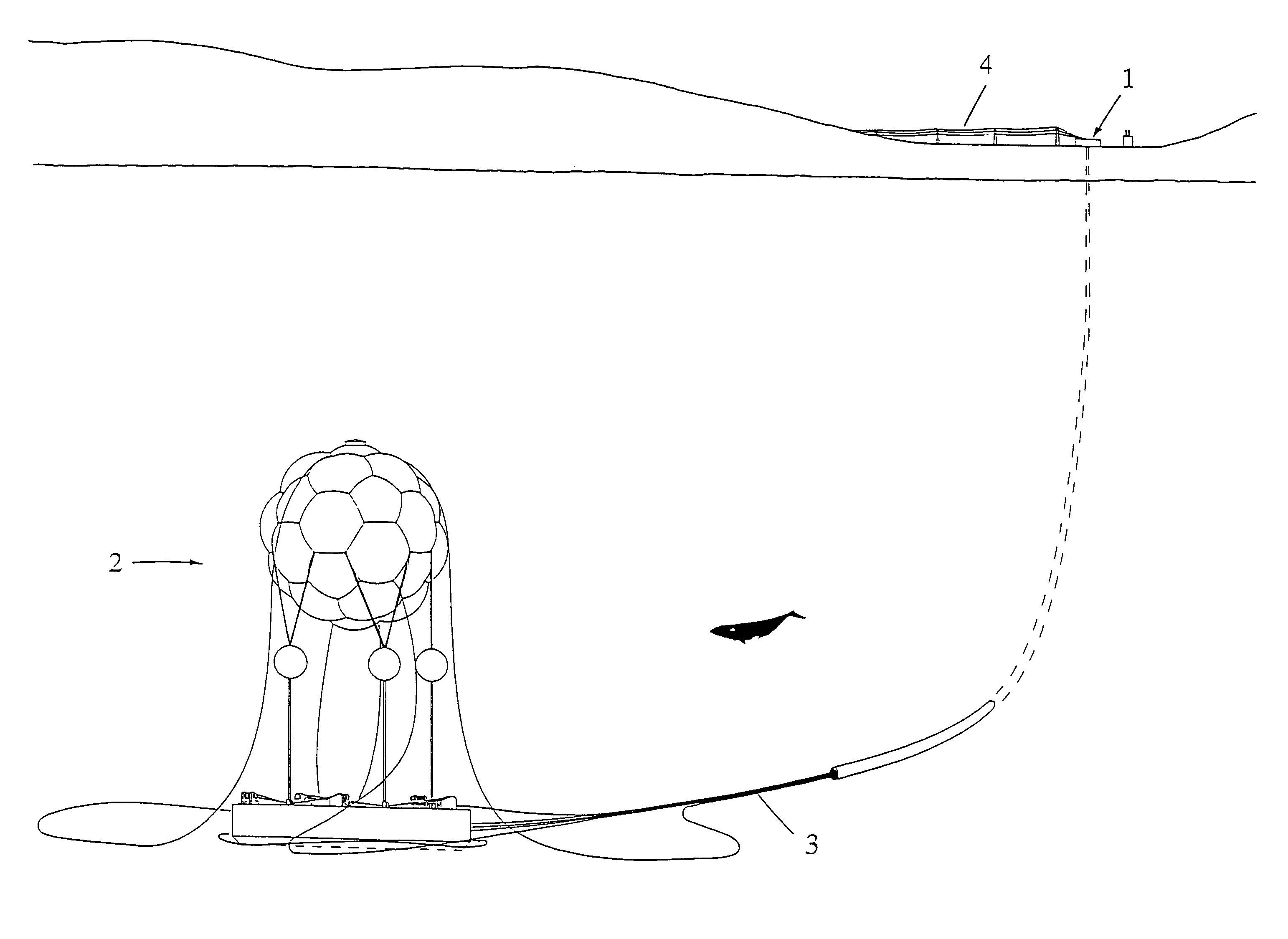
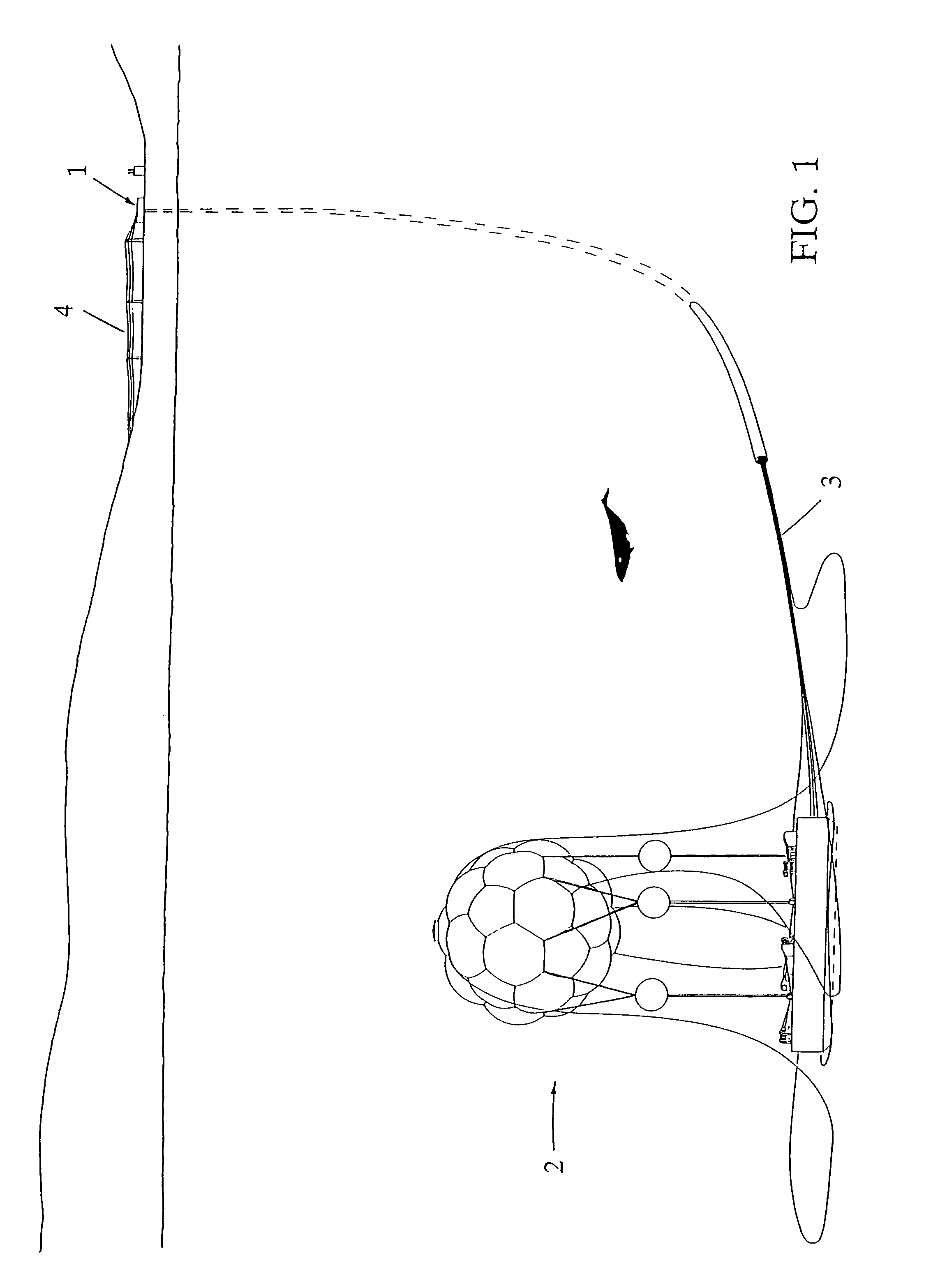
[0029]Referring now to the drawings, FIG. 1 is a single point perspective of a seafloor power station showing a manned shore facility (1) with control, hydraulic pump and other support rooms in a building with transformers, vacuum tanks and standby generators adjacent. One Unit (2) is shown through the water on the seafloor. Electric lines and hoses (3) to the facility deliver power from the Units' generators, operate the mats' winches from the pumproom, and maintain a vacuum in the hull; the vacuum hoses also serve as conduits for fibre optic and other control circuits.

[0030]Lines (4) from the transformers send power to a high voltage grid. If the Units are farther offshore, economics may indicate locating the facility on an island or platform, from which only the high voltage lines would go ashore.

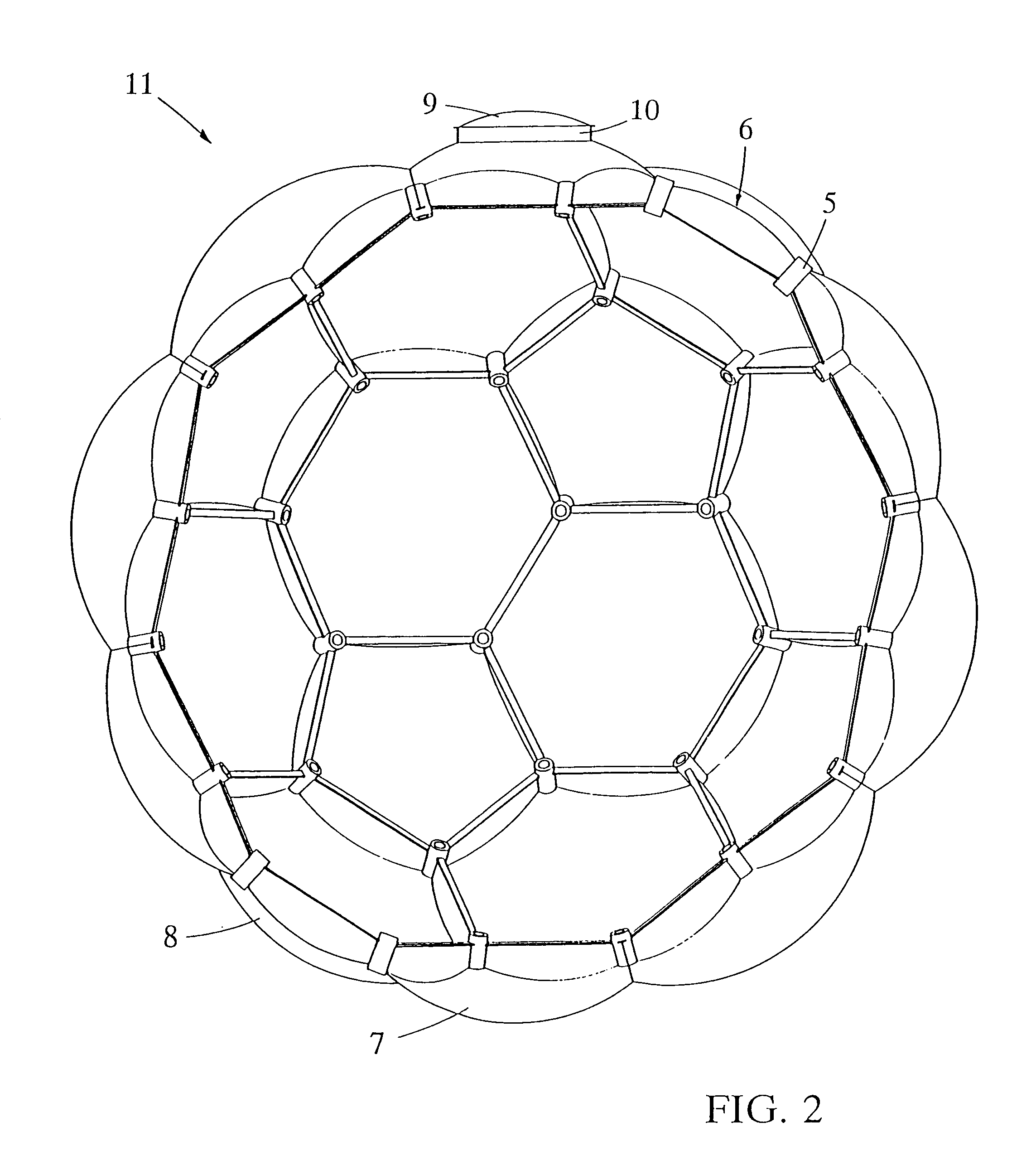
[0031]FIGS. 2-4 show the steel hull (11) structure in half section and detail, with sixty radially oriented tubes (5) with ninety standard beams (6) twelve pentagon based domes (7) and t...


PUM


Abstract

The Seafloor Power Station is one or more unmanned electric power generating Units (2) sending power to and operated from existing coastal sites by a manned facility (1) by connecting lines and hoses (3) delivering power to a grid by lines (4). Each Unit's hull (11) maintained in a vacuum, contains both nuclear steam and electricity generating systems. The hull functions as overpressure containment and as condenser in the event of a loss of coolant accident or other steam release. The Units operate submerged in very cold water, with depth set by remotely controlled vertical mooring systems, mounted on gravity mats (27). A Unit must be surfaced by its mooring system to refuel the reactor, an action both conspicuous and public, enabling international oversight of the fuel disposition.

Description

[0001]This application is a continuation of co-owned and U.S. patent application Ser. No. 10 / 647,081 filed Aug. 21, 2003 now abandoned of the same title, which is a continuation of co-owned and U.S. patent application Ser. No. 09 / 840,653 filed Apr. 23, 2001 now abandoned and entitled “A SEAFLOOR POWER STATION”, each of which are incorporated herein by reference in their entirety.BACKGROUND OF THE INVENTION[0002]This invention relates to electric power generating stations, and more particularly to a deeply submersible, and surfacable, condensing containment system for a nuclear powered electricity generator.[0003]For the past three decades proposals were developed for siting nuclear power plants offshore to take advantage of the virtually limitless supply of cooling seawater and available seafloor real estate. These sites also satisfied the goal of removing power plants from population centers, yet could be closer to urban areas than could be achieved by siting in rural land areas.[0...

Claims


Application Information

Patent Timeline
IPC IPC(8): G21C9/00B63B21/00E02D23/02G21C1/00F03B13/10G21C13/00G21C13/024G21C23/00G21D1/00
CPCG21C13/00G21C13/024G21D1/00G21Y2002/301G21Y2002/304G21Y2002/50G21Y2004/30Y02E30/40Y10S376/909Y10S376/912Y02E30/30Y02E30/00Y02E10/20F03B13/10
Inventor HAYMAN, III, W. Z. ZACK
Owner HAYMAN III W Z ZACK
Learn More