
Method and apparatus for the digitization of and for the data compression of analog signals

a technology of analog signals and data compression, applied in the field of methods and apparatus for the digitization of analog signals and methods and apparatus for data compression of analog signals, can solve the problems of large differences in the original waveform, large signal delay, and inability to use signal coding methods of this type in many areas of application, and achieve the effect of improving quality

Inactive Publication Date: 2011-07-12
SENNHEISER ELECTRONICS GMBH & CO KG +1
View PDF5 Cites 4 Cited by
  • Summary
  • Abstract
  • Description
  • Claims
  • Application Information

AI Technical Summary

Benefits of technology

The present invention provides a method and apparatus for the digitization and compression of analog signals with improved quality. The method involves digitizing analog source signals, transforming them from the time domain to the spherical domain, and logarithmically quantizing the radius in the spherical domain. The apparatus includes means for digitization, transformation, and quantization. The invention also provides a waveform-preserving method that meets requirements such as low data rate, high dynamic range, high signal-to-noise ratio, insensitivity to signal parameters, and small signal delay. The combination of differential pulse code modulation and spherical logarithmic quantization achieves effective data reduction with a high signal-to-noise ratio.

Problems solved by technology

Normally, a signal processing using irrelevance leads to a reconstructed waveform that differs greatly from the original waveform and, moreover, is often afflicted by extensive signal delay (e.g., because of spectral transformations or equivalent block-based methods).
The transmission quality in a method of the type mentioned above cannot be measured by a 10 log10 signal / noise ratio (SNR) in the conventional way; rather, it must be determined by time-consuming listening tests by trained personnel.
However, signal coding methods of this type are totally unusable for many areas of application (e.g., metrology, recording of waveforms for further signal processing at a later time, real-time signal transmission using digital modulation methods that do not permit significant signal delay, e.g., for wireless digital stage microphones).

Method used

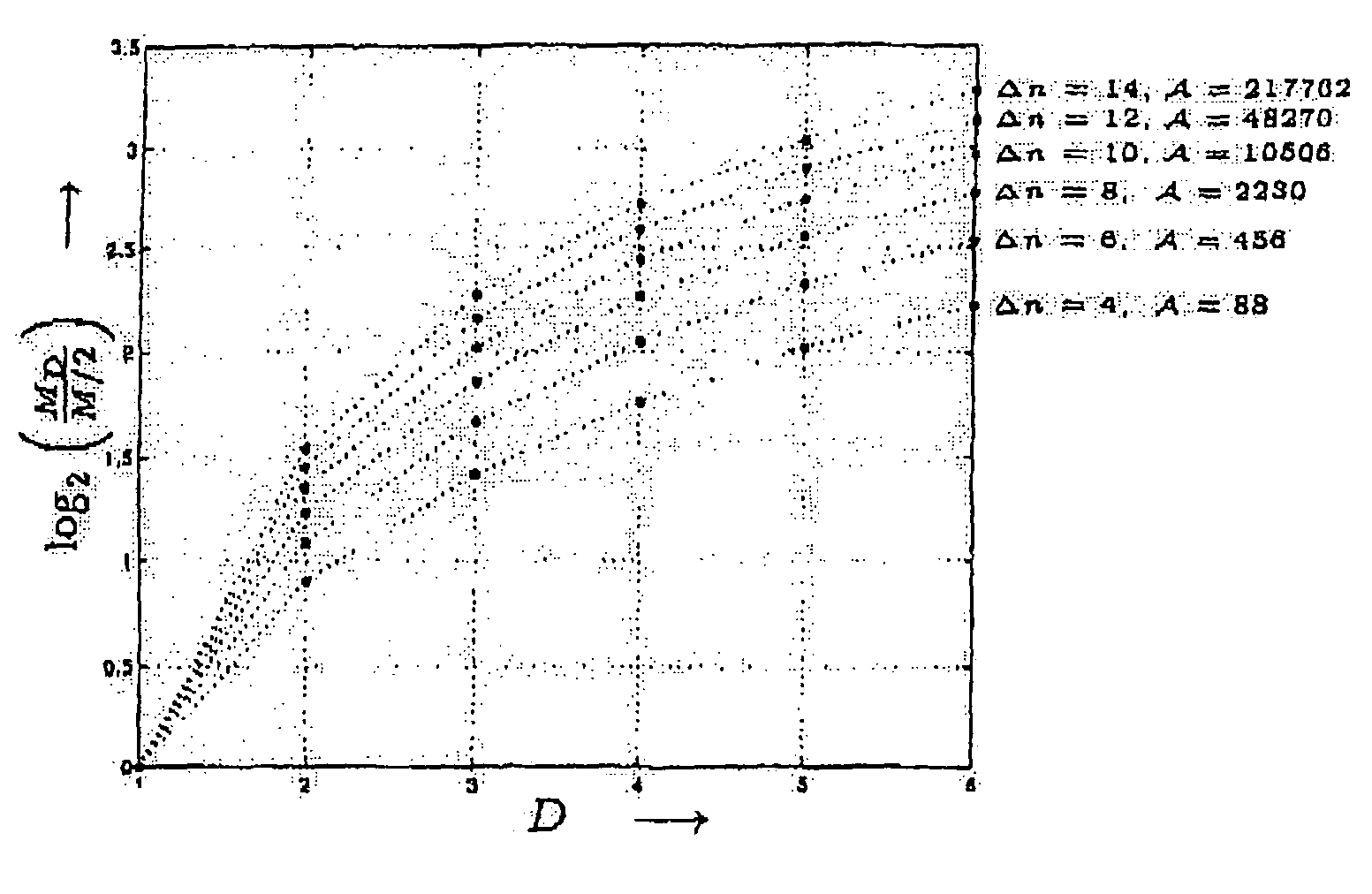
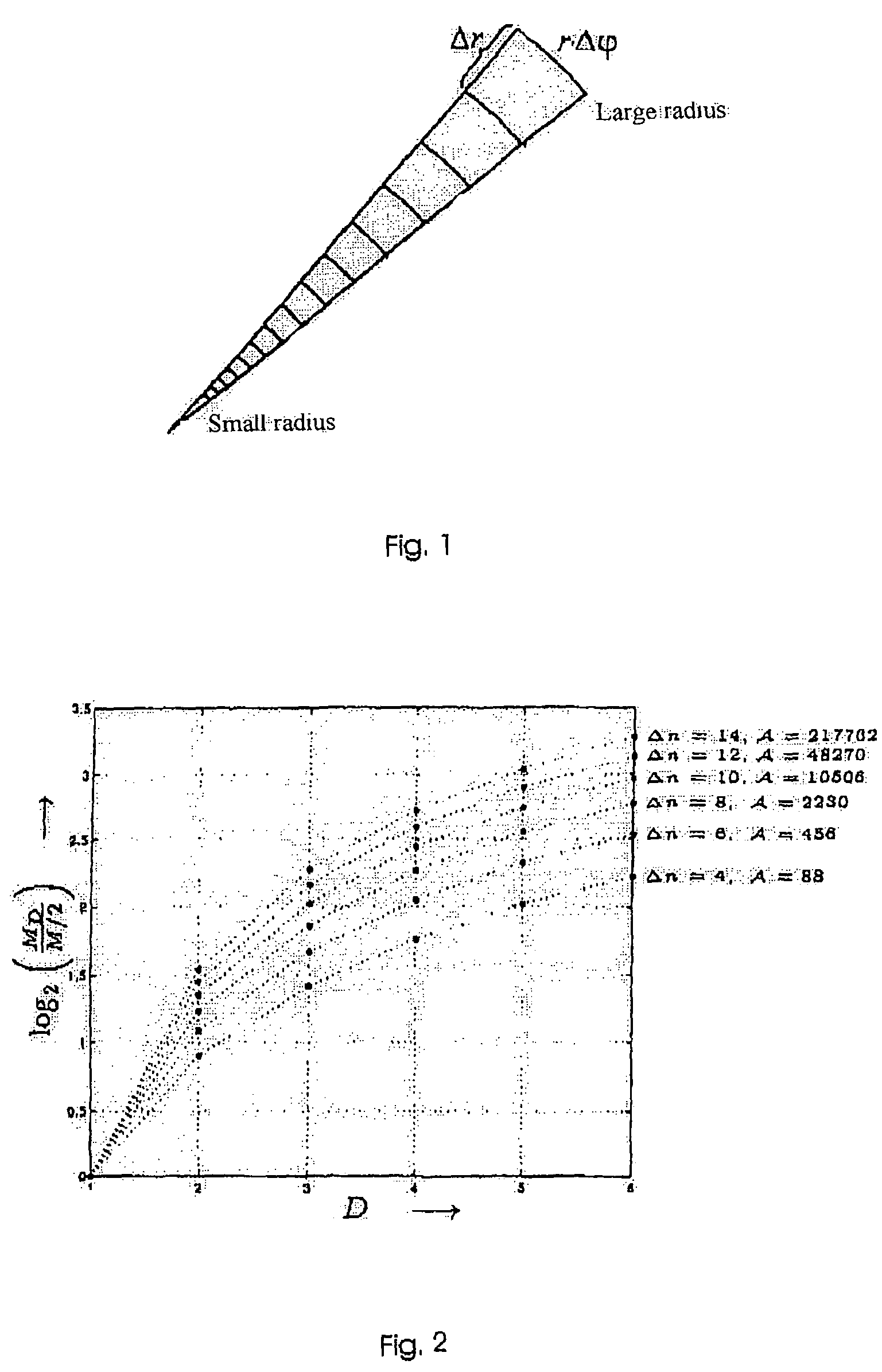
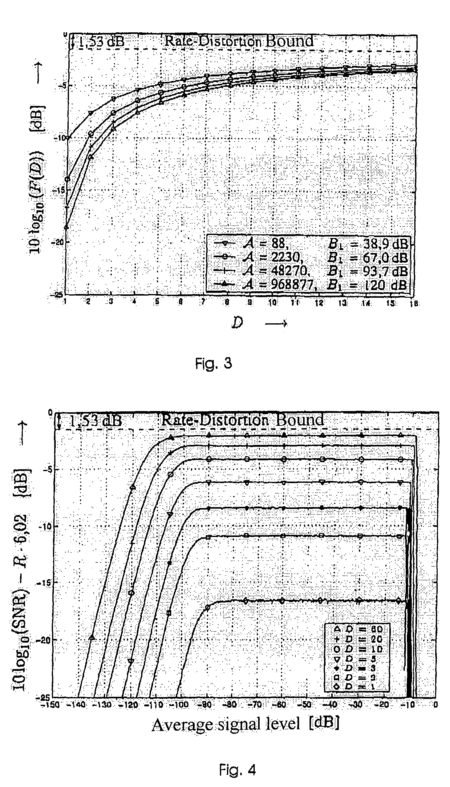

Image

  • Method and apparatus for the digitization of and for the data compression of analog signals
  • Method and apparatus for the digitization of and for the data compression of analog signals
  • Method and apparatus for the digitization of and for the data compression of analog signals

Examples


Embodiment Construction

[0024]The aim of the logarithmic quantization is a high dynamic of the quantizer, that is, a wide range of the average signal level in which the SNR and, therefore, the maximum relative quantization error

[0025]Δqi / 2ri

is constant, wherein Δqi is the width of the ith quantization interval and ri is the respective reconstruction value. This aim leads to logarithmic quantization, e.g., within the meaning of the A-law according to K. Tröndle, R. Weiβ, Introduction to Pulse Code Modulation, Oldenbourg Verlag, Munich, 1974. For the range of average modulation, the following signal / noise ratio is given for R>>1 according to N. S. Jayant, P. Noll, Digital Coding of Waveforms, Prentice-Hall, Englewood Cliffs, N.J., 1984:

[0026]10⁢⁢log10⁡(S⁢⁢N⁢⁢R)=R·6.02⁢⁢dB+10⁢⁢log10⁢3(1+ln⁡(A))2,(1)

where R is the average rate of quantization (bits / sample) and A represents the usual parameters of logarithmic quantization; that is, the maximum relative error is constant for samples with an amount greater than 1...


PUM


Abstract

The invention is based on the idea of providing a method for high-resolution, waveform-preserving digitization of analog signals, wherein conventional scalar logarithmic quantization is transferred to multi-dimensional spherical coordinates, and the advantages resulting from this, e.g., a constant signal / noise ratio over an extremely high dynamic range with very low loss with respect to the rate-distortion theory. In order to make use of the statistical dependencies present in the source signal for an additional gain in the signal / noise ratio, the differential pulse code modulation (DPCM) is combined with spherical logarithmic quantization. The resulting method achieves an effective data reduction with a high long-term and short-term signal / noise ratio with an extremely small signal delay.

Description

CROSS-REFERENCE TO RELATED APPLICATIONS[0001]This application claims priority of International Application No. PCT / EP2004 / 008217, filed Jul. 23, 2004 and German Application No. 103 34 357.1, filed Jul. 25, 2003, the complete disclosures of which are hereby incorporated by reference.BACKGROUND OF THE INVENTION[0002]a) Field of the Invention[0003]The present invention is directed to a method and apparatus for the digitization of analog signals and a method and apparatus for data compression of analog signals.[0004]b) Description of the Related Art[0005]In many fields of digital information transmission there exists the common goal of transporting an initially analog source signal (measuring, studio-quality audio signal processing, and so on) to a receiver while making use of the advantages of digital transmission in order to reproduce this analog source signal in the receiver in the form of an analog output signal. For this purpose, the analog signal must be digitized and quantized on...

Claims


Application Information

Patent Timeline
Patent Type & Authority Patents(United States)
IPC IPC(8): G10L21/00G10L25/12H03M1/12H03M7/00H03M7/30
CPCH03M7/3046H03M7/3082G10L25/12
Inventor HAUPT, AXELSCHMITT, VOLKERHUBER, JOHANNESMATSCHKAL, BERND
Owner SENNHEISER ELECTRONICS GMBH & CO KG
Learn More