Cryostat having a magnet coil system, which comprises an LTS section and an HTS section, which is arranged in the vacuum part

a technology of magnet coils and cryostats, which is applied in the direction of superconducting magnets/coils, using reradiation, magnetic materials, etc., can solve the problems of evaporating helium not being able to escape quickly enough from the porous material, hts being exploded, and a large amount of pressure built up in the pores, etc., to achieve convenient and fast evaporation, improve cooling and operation safety, and simplify the effect of recurren

Inactive Publication Date: 2011-07-19
BRUKER BIOSPIN
View PDF11 Cites 15 Cited by
  • Summary
  • Abstract
  • Description
  • Claims
  • Application Information

AI Technical Summary

Benefits of technology

[0013]All these effects can be prevented with the cryostat configuration in accordance with the invention. The HTS section or sections of the magnetic coil system and thereby all of the HTS material is disposed in a vacuum portion of the cryostat between the inner wall of the helium tank and the room temperature bore. Clearly, no liquid helium is present in that vacuum portion. Moreover, the vacuum portion of an NMR cryostat is usually one integral piece. For example, the HTS section has an outer circularly cylindrical periphery which seats on the likewise circularly cylindrical inner wall of the helium tank and is thereby positively connected to the radially inner LTS section, which, if appropriate, seats on this wall from the helium side by means of small spacers. Since the HTS materials of the HTS section are in vacuum and do not come in contact with liquid helium, evaporation of helium, which has seeped into the inner portions of the HTS material is thereby avoided. The ballooning effect of the HTS material is therefore prevented.
[0029]Alternative thereto, the side of the wall of the additional helium tank facing the room temperature bore can be radially closer to the room temperature bore than the wall of the helium facing the room temperature bore. This embodiment permits a straightforward introduction of the current leads into the flat floor plate of the additional (upper) helium tank. The volume of the additional helium tank can thereby be increased which leads to a longer holding time for the helium. It is additionally preferred when the wall of the additional helium tank facing the room temperature bore is aligned with the inner bore of the HTS section.

Problems solved by technology

If the warming occurs too rapidly, the evaporating helium cannot escape quickly enough from the porous material and a substantial amount of pressure is built up within the pores of the HTS.
Since the HTS material is ceramic and relatively brittle, the HTS can be explode in consequence of this pressure.

Method used


Image

  • Cryostat having a magnet coil system, which comprises an LTS section and an HTS section, which is arranged in the vacuum part
  • Cryostat having a magnet coil system, which comprises an LTS section and an HTS section, which is arranged in the vacuum part
  • Cryostat having a magnet coil system, which comprises an LTS section and an HTS section, which is arranged in the vacuum part

Examples


first embodiment

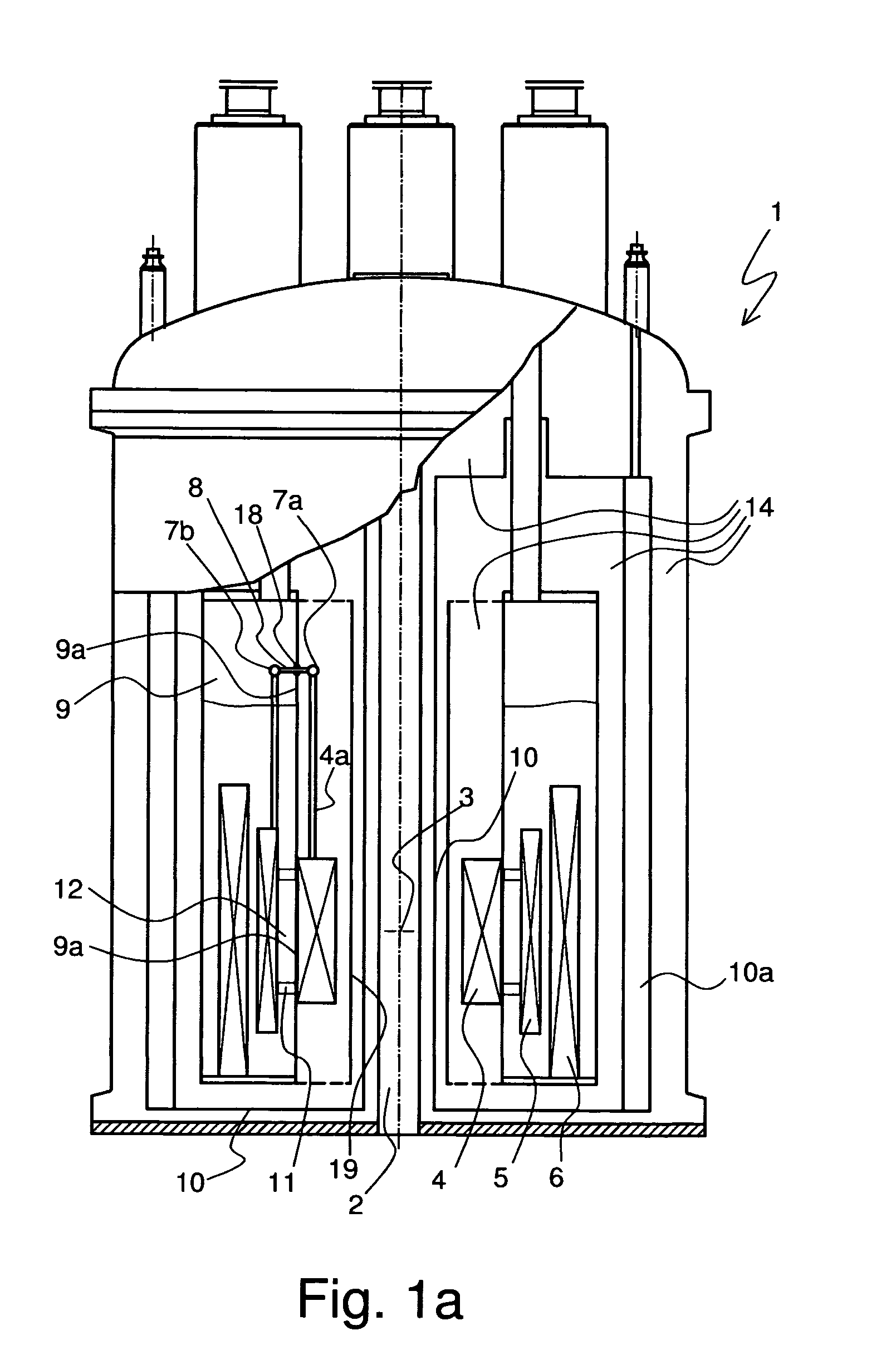
[0037]FIG. 1a shows a cryostat 1 in accordance with the invention. The cryostat 1 has a room temperature bore 2 in which a measuring volume 3 for a sample is provided. The measuring volume 3 is located in the center of a magnetic coil system, which is formed by three solenoid-shaped coil section 4, 5, 6. The radially innermost coil section 4 has a wounding made from high temperature superconductor (HTS). The middle coil section 5 is wound with Nb3Sn wire and the outer most coil section 6 is wound with NbTi wire. The coil sections 5, 6 therefore represent low temperature superconductor (LTS) coil sections. The coil sections 4, 5, 6 are electrically connected to each other in series, as is shown in an exemplary fashion by means of superconducting joints 7a and 7b. At joint 7a, the high HTS material of a lead 4a is connected to a HTS coil section 4 by means of an adaptor section 8 made from NbTi. At joint 7b, the adaptor member 8 is connected to the Nb3Sn wire of the LTS section 5. The...

second embodiment

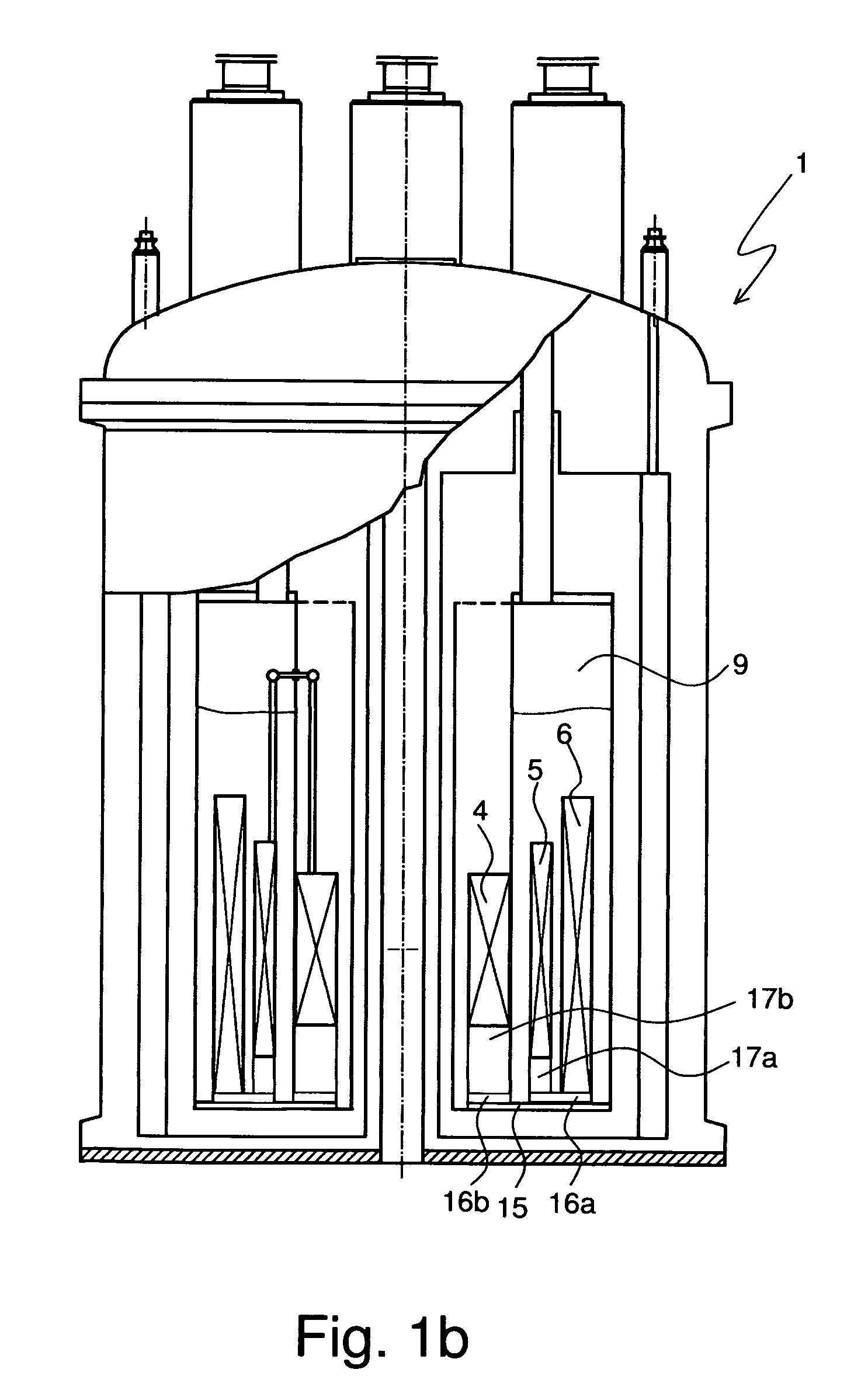
[0042]the cryostat 1 in accordance with the invention is shown in FIG. 1b. This embodiment substantially corresponds to that of FIG. 1a, however, entails a particular anchoring of coil sections 4, 5, 6.

[0043]A radially outer portion of a floor plate 15 forms the lower wall of the helium tank 9. The floor plate 15 extends in a radially inward direction up to beneath the HTS section 4. Two ring flanges 16a, 16b are attached to the floor plate 15. The LTS section 6 is directly attached to the radially outer ring flange 16a and the LTS section 5 is indirectly attached thereto by means of a coil support 17a. The HTS section is attached to the radially inner ring flange 16b by means of a coil support 17b. The floor plate 15 is preferentially formed from a single piece. This configuration permits simultaneous handling of all coil sections 4, 5 and 6 during assembly of the cryostat 1 by means of the common floor plate 15.

third embodiment

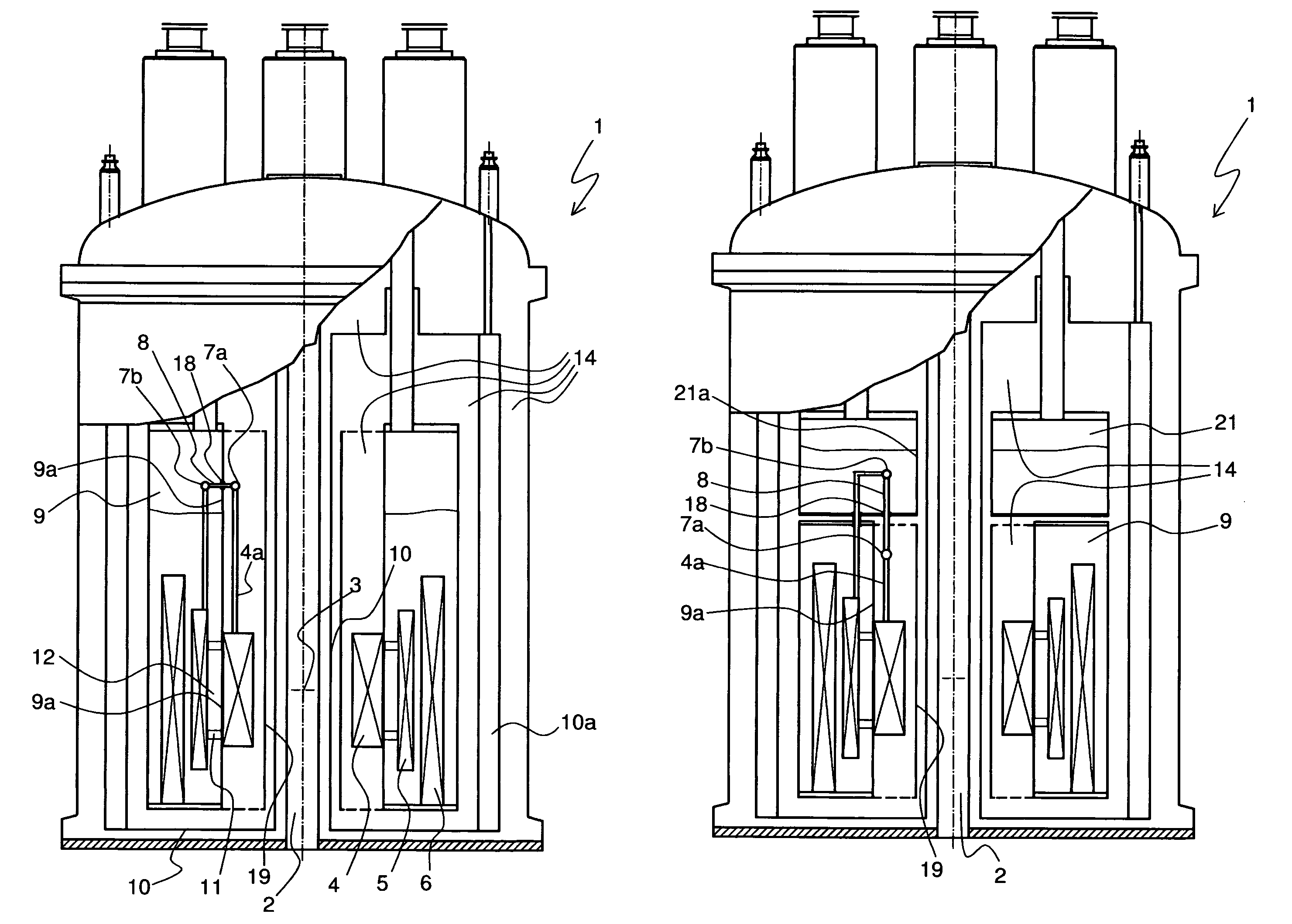
[0044]cryostat 1 in accordance with the invention shown in FIG. 2 corresponds substantially to the cryostat of FIG. 1. However, cryostat 1 of FIG. 2 has helium tank 9 as well as an additional, upwardly disposed helium tank 21. Both helium tanks 9, 21 contain helium at different temperatures. The lower helium tank 9 is at approximately 2 K and the upper additional tank 21 at approximately 4 K. Cryostats 1 of this type are preferentially utilized to produce very high magnetic fields, in particular in high field NMR systems.

[0045]In the embodiment shown in FIG. 2, the additional helium tank 21 extends further in the inward direction (towards the room temperature bore 2) than does the lower helium tank 9, wherein a feed through 18 for the adaptor piece 8 is disposed on the floor of the additional helium tank 21. The inner wall 21a of the additional helium tank 21 which faces the room temperature bore 22 is located at an equal radial separation from the room temperature inner bore 2 as t...


PUM

PropertyMeasurementUnit
temperatureaaaaaaaaaa
pressureaaaaaaaaaa

Abstract

A cryostat (1) with a magnet coil system including superconductors for the production of a magnet field B0 in a measuring volume (3) within a room temperature bore (2) of the cryostat has a plurality of radially nested solenoid-shaped coil sections (4, 5, 6) which surround the room temperature bore and which are electrically connected in series, at least one of which being an LTS section (5, 6) with a conventional low temperature superconductor (LTS) and at least one of which being an HTS section (4) including a high temperature superconductor (HTS), wherein the LTS section (5, 6) is located in a helium tank (9) of the cryostat (1) along with liquid helium at a helium temperature TL. The apparatus is characterized in that the HTS section (4) is disposed radially within the LTS section (5, 6) in a vacuum portion of the cryostat and is separated from the LTS section (5, 6) by the helium tank (9) wall (9a) facing the room temperature bore. The HTS coil section can be reliably used in the cryostat over a long period of time (FIG. 1a).

Description

[0001]This application is the national stage of PCT / EP2007 / 001924 filed on Mar. 7, 2007 and also claims Paris Convention priority to DE 10 2006 012 509.6 filed Mar. 18, 2006.BACKGROUND OF THE INVENTION[0002]The invention concerns a cryostat having a magnetic coil system including superconducting materials for generation of a magnetic field B0 within a measurement volume, the magnet system having a plurality of radially nested solenoid-shaped coil sections connected in series at least one of which is an LTS section of a conventional low temperature superconductor (LTS) and with at least one HTS section of a high temperature superconductor (HTS), wherein the LTS portion is located in a helium tank of the cryostat having liquid helium at a helium temperature TL.[0003]Cryostats of this kind are e.g. disclosed in DE 10 2004 007 340 A1.[0004]By way of example, nuclear magnetic resonance systems, in particular spectrometers, require very strong, homogenous and stable magnetic fields. The s...

Claims


Application Information

Patent Timeline
Patent Type & Authority Patents(United States)
IPC IPC(8): H01F7/00H01F6/00H01F1/00G01V3/00H01F41/00
CPCG01R33/3815H01F6/04H01F6/06
Inventor KASTEN, ARNE
Owner BRUKER BIOSPIN
Why Eureka
Try Eureka