
Method for reducing the reactive power requirement of a fundamental frequency clocked power supply side converter under no load and with low motor loading

a technology of fundamental frequency clocked power supply and reactive power, which is applied in the direction of electric variable regulation, process and machine control, instruments, etc., can solve the problems of high motor bearing current, large reactive power requirement, and high oscillating curren

Active Publication Date: 2011-07-19
SIEMENS AG
View PDF15 Cites 2 Cited by
  • Summary
  • Abstract
  • Description
  • Claims
  • Application Information

AI Technical Summary

Benefits of technology

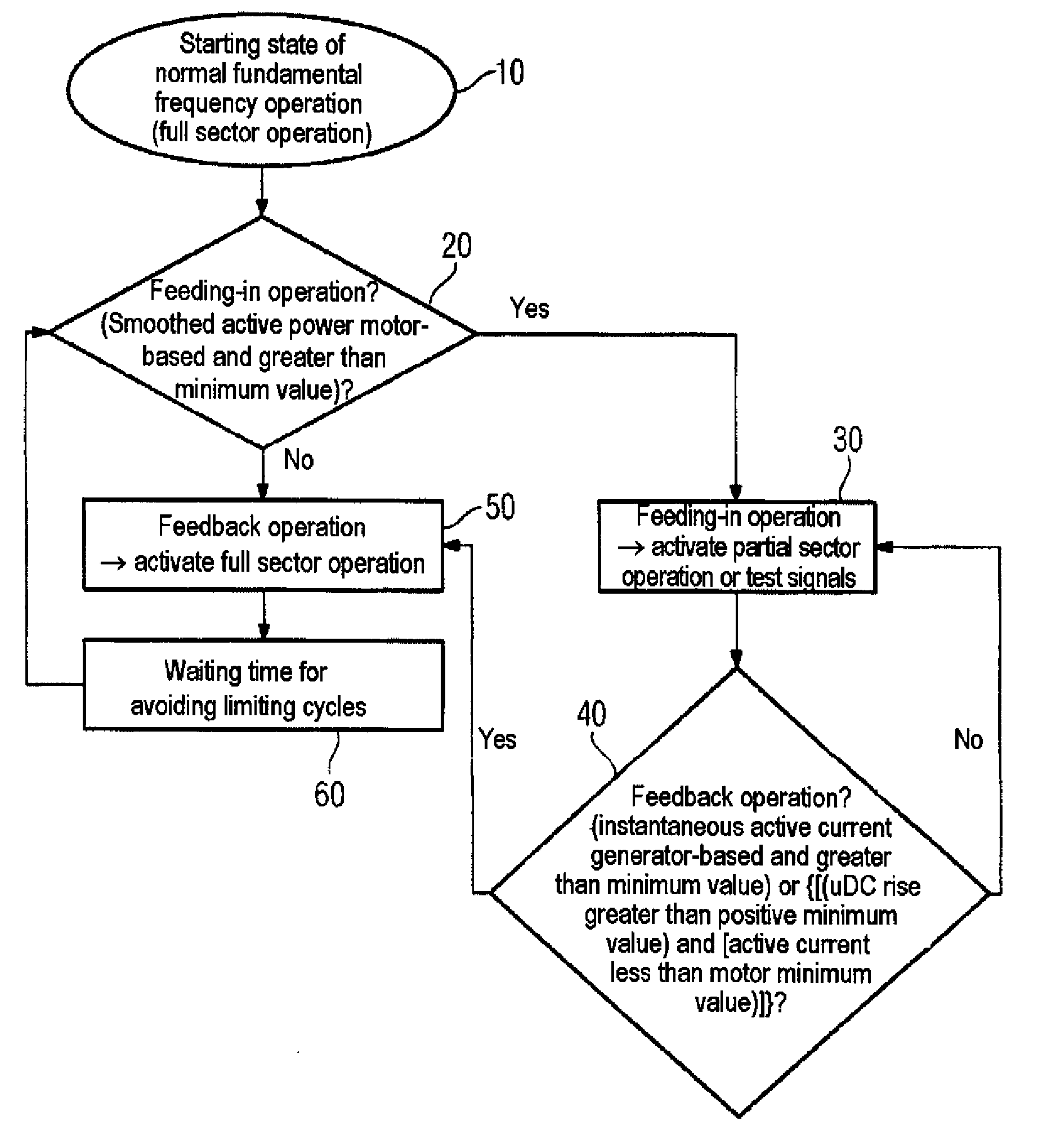
[0001]The invention relates to a method for reducing the reactive power requirement of a fundamental frequency clocked power supply side converter under no load and with low motor loading.

Problems solved by technology

Since high frequency clocking of the semiconductor switches, which can also be referred to as current valves, is not effected, this gives rise for example to low switching losses, the possibility of using simple and cost-effective commutation inductors and power supply filters, little excitation of system oscillations which can lead for example to high motor bearing currents.
A considerable disadvantage of fundamental frequency clocked operation, however, is that during no load or during weak loading of the converter, a relatively large reactive power requirement arises and a high oscillating current occurs.
This leads to a loading of the electrical power supply for the user and to an apparently higher current consumption in association with the resultant disadvantages with regard to the energy costs.
One way of eliminating this disadvantage has hitherto been achieved on the one hand by using large commutation inductances LC, associated with high costs for the commutation inductances LC and also a high voltage drop in the commutation inductances LC.
On the other hand, a small intermediate circuit capacitance CDC is used, associated with a small or even lacking buffer effect, as a result of which it is not possible to connect large multi-axle drives, for example, to the intermediate circuit.
If neither large commutation inductances nor small intermediate circuit capacitances are appropriate, the user hitherto has had to accept the high apparent power requirement in conjunction with the high costs arising as a result.

Method used


Image

  • Method for reducing the reactive power requirement of a fundamental frequency clocked power supply side converter under no load and with low motor loading
  • Method for reducing the reactive power requirement of a fundamental frequency clocked power supply side converter under no load and with low motor loading
  • Method for reducing the reactive power requirement of a fundamental frequency clocked power supply side converter under no load and with low motor loading

Examples


Embodiment Construction

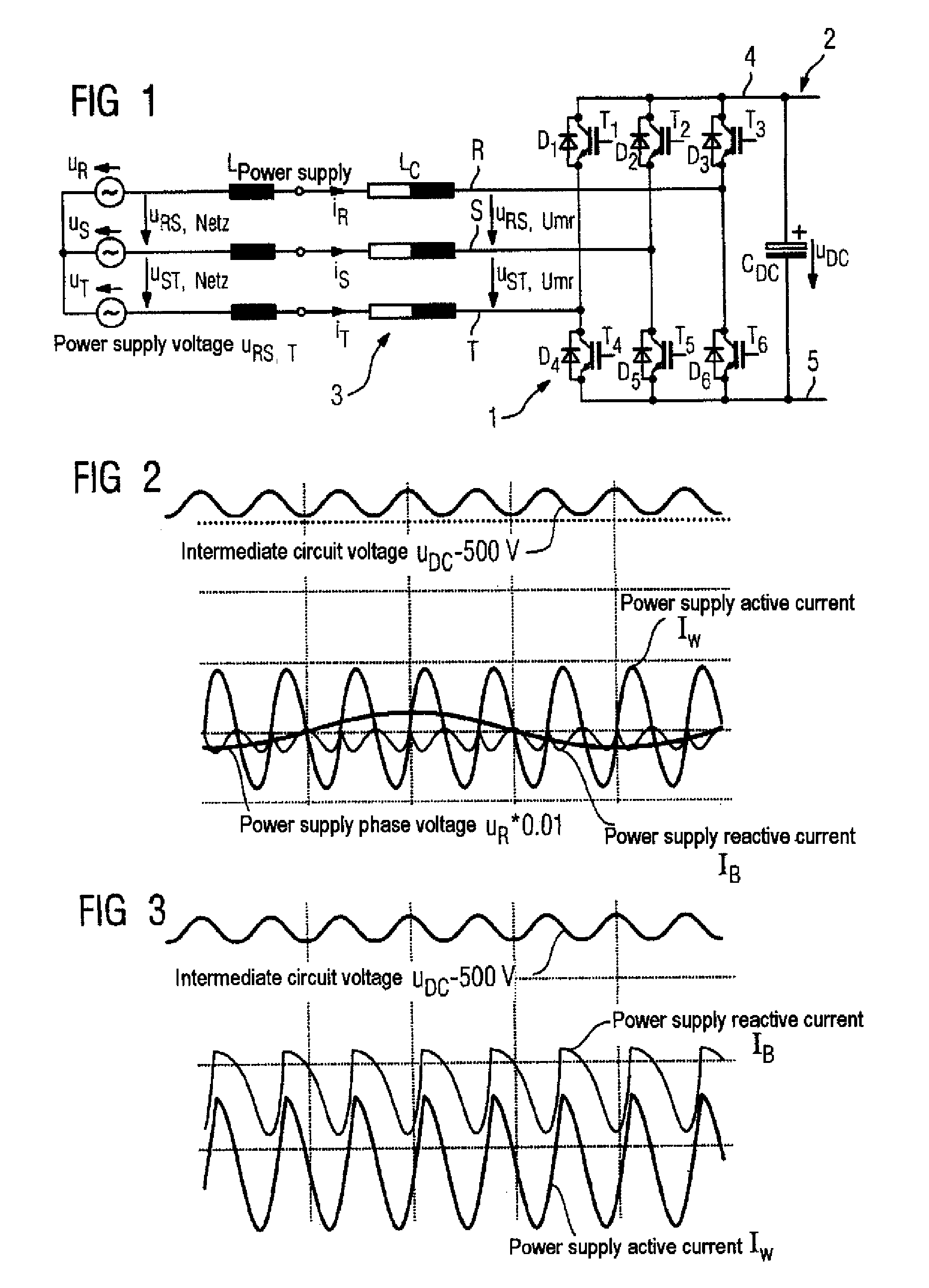
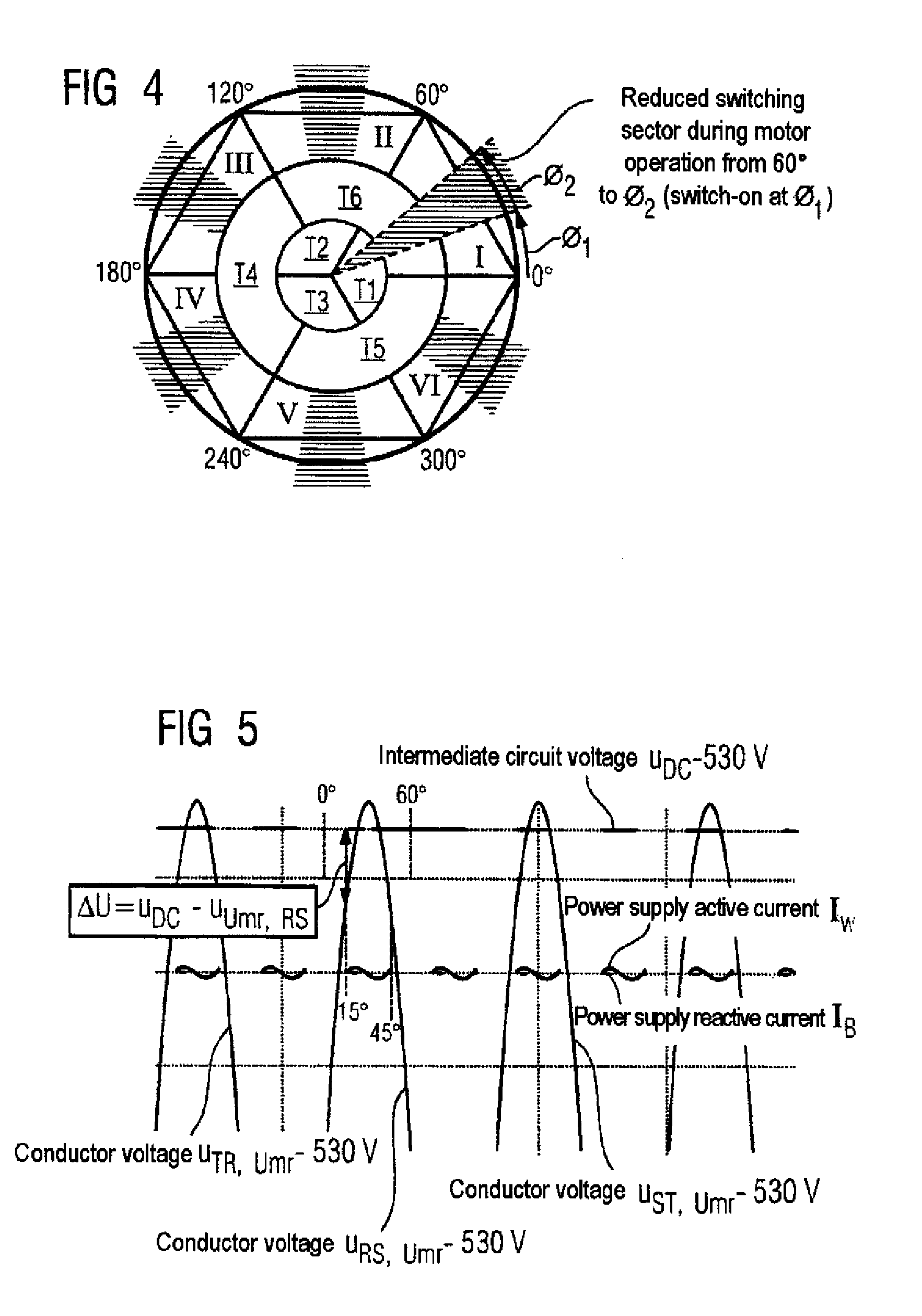
[0073]For the preferred solution route, a transformation of the three-phase power supply current into its active component and into its reactive component is used as illustrated schematically in FIG. 2. The representation of the currents and voltages as space vectors is chosen for this purpose. The space vector xαβ in the α-β coordinate system results from the components of the phases R, S, T—phase components hereinafter—as follows:

[0074]xαβ=xα+jxβ=[xαxβ]=23⁡[1-12-120⁢32-32]⁡[xRxSxT].(a)

[0075]This definition applies both to the space vector uαβ of the power supply voltages uR, uS, uT and to the current space vector iαβ of the phase currents iR, iS, iT, where x in equation (a) is replaced by u and i, respectively. The time dependence is not explicitly incorporated in this case. The space vector iαβ rotates with the power supply frequency about the origin of the α-β coordinate system. Transformation into a coordinate system which rotates with the power supply frequency yields the stea...


PUM


Abstract

The invention relates to a method for reducing the idle current requirement of a base frequency clocked supply side converter (1) on idle and with low motor loads, provided with controllable semiconductors (T1,T2,T3,T4, T5,T6), wherein the base frequency clocking of the semiconductor switches (T1,T2,T3,T4,T5,T6) occurs depending on the desired direction of flow of power. A converter (1) for carrying out said method is also disclosed.

Description

[0001]The invention relates to a method for reducing the reactive power requirement of a fundamental frequency clocked power supply side converter under no load and with low motor loading.[0002]Electrical installations which, from the standpoint of the three-phase power supply, operate as load at times and as generator at times are usually connected to the three-phase power supply via a so-called intermediate circuit. One example of such an electrical installation is a centrifuge in a sugar factory. Installations operated in particular only occasionally and serving for decentralized electrical energy generation, such as relatively small wind power or solar installations, for instance, are likewise connected to the three-phase power supply via an intermediate circuit.[0003]FIG. 1 schematically illustrates the construction and also the connection of a known converter 1 regulating an intermediate circuit 2 to a three-phase power supply 3. The converter 1 comprises a plurality of semico...

Claims


Application Information

Patent Timeline
IPC IPC(8): H02M5/45
CPCH02J3/1892H02M1/4216H02M1/4233Y02B70/126Y02B70/10
Inventor BENESCH, NORBERT
Owner SIEMENS AG
Learn More