Process for producing clean liquid fuels from coal waste

a technology of coal waste and liquid fuel, which is applied in the field of coal gasification, can solve the problems of large piles of ash, acid-leaching, and messy ash, and achieve the effect of lowering the melting point of ash

Inactive Publication Date: 2011-08-02
RICH JR JOHN W
View PDF17 Cites 4 Cited by
  • Summary
  • Abstract
  • Description
  • Claims
  • Application Information

AI Technical Summary

Benefits of technology

[0004]The present invention is directed to a process for producing ultra clean liquid fuel from abandoned mine waste. A feedstock is prepared from water and coal mine waste having relatively high ash (non-carbonaceous matter) content. Foundry slag is added to the feedstock as a fluxant to adjust the melting behavior of the ash in the feedstock. Preferably, the fluxant is blast furnace slag provided in a particle size of less than about 150μm and is provided in an amount sufficient to lower the melting point of the ash in the feedstock by at least about 200° F. The feedstock is admitted with a flow of oxygen into a pressurized chamber of an entrained flow gasifier in which the feedstock and oxygen are heated to produce a synthetic gas from a coal component of the feedstock and molten slag from the ash and fluxant components of the feedstock. The molten slag is of a viscosity to freely flow out of the gasifier through an exit port in the bottom of the gasifier. The synthetic gas is separately discharged from the gasifier through an outlet located near the top of the gasifier. Thereafter, the synthetic gas is provided to a slurry phase vessel having a catalyst to produce paraffin. The paraffin is used to produce an ultra clean liquid fuel.

Problems solved by technology

The waste coal remains in vast, messy, acid-leaching piles that blight the landscape and provide a nasty environmental legacy from the past mining operations.

Method used


Image

  • Process for producing clean liquid fuels from coal waste
  • Process for producing clean liquid fuels from coal waste

Examples


Embodiment Construction

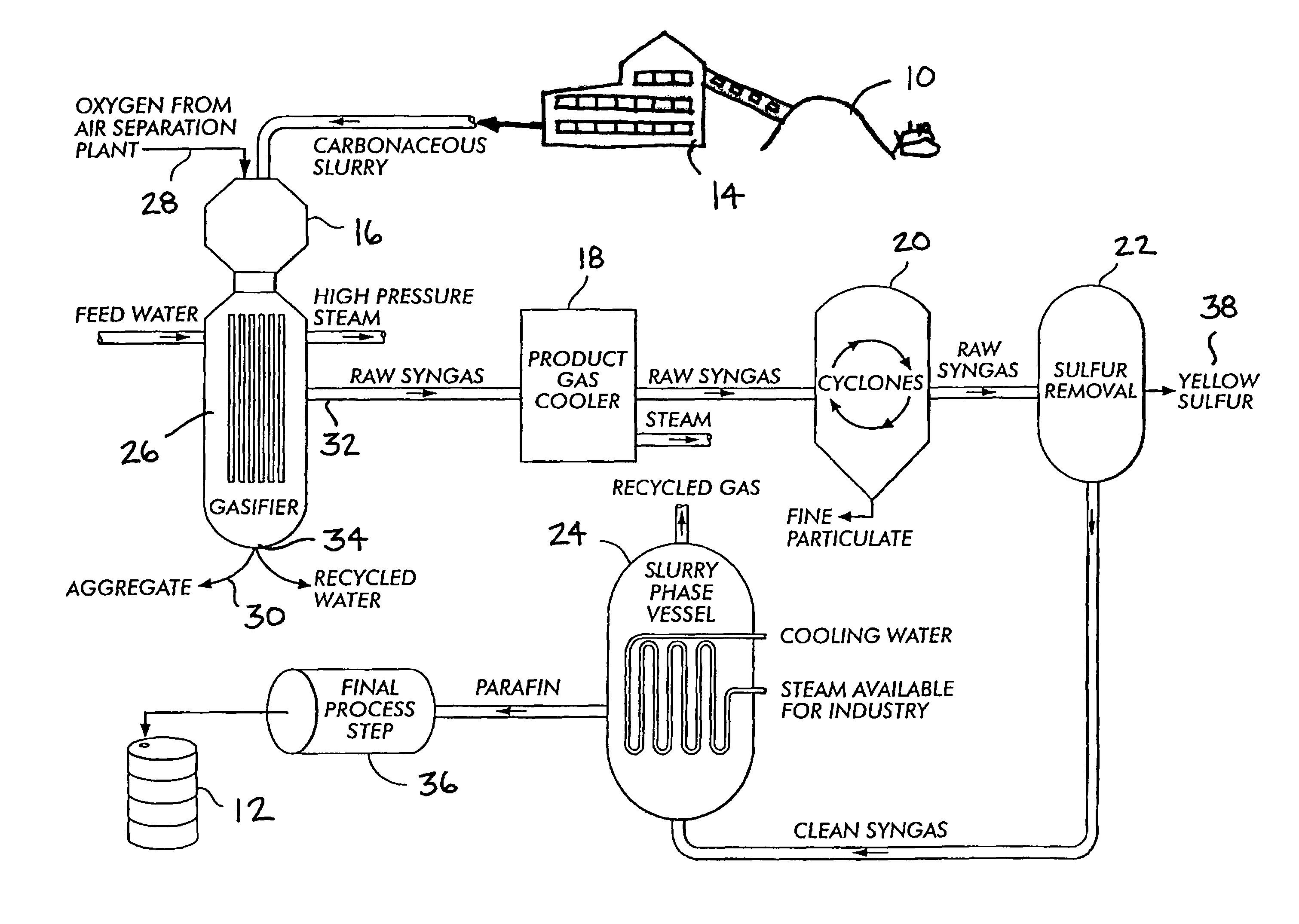
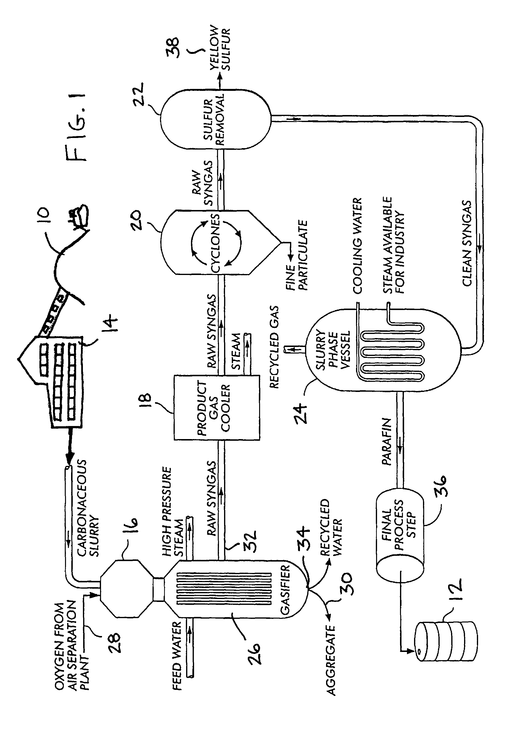
[0006]The present invention relates to a coal gasification and liquefaction process utilized to produce ultra-clean liquid fuels. The process preferably utilizes abandoned mine waste 10 to produce a slurry of carbonaceous material that is ultimately transformed into a liquid fuel 12. The process provides a means for eliminating millions of tons of coal mining waste and for reclaiming abandoned mine land. The basic steps of the process include feedstock preparation 14, synthetic gas production and treatment 16, 18, 20 and 22, and Fischer-Tropsch synthesis 24.

[0007]Gasifying coal involves mixing a coal waste feedstock with oxygen within a pressurized chamber 26 and heating it therein to above 2,000° F. to produce a synthetic gas, which is basically a blend of hydrogen and carbon monoxide. The synthetic gas can be used in power plants for the production of electricity or it can be converted into a number of different liquid fuels, for instance, via a Fischer-Tropsch chemical process.

[0...


PUM

PropertyMeasurementUnit
particle sizeaaaaaaaaaa
melting pointaaaaaaaaaa

Abstract

The present invention is directed to a process for producing ultra clean liquid fuel from abandoned mine waste. A feedstock is prepared from water and coal mine waste having relatively high ash (non-carbonaceous matter) content. Foundry slag is added to the feedstock as a fluxant to adjust the melting behavior of the ash in the feedstock. Preferably, the fluxant is blast furnace slag provided in a particle size of less than about 150 μm and is provided in an amount sufficient to lower the melting point of the ash in the feedstock by at least about 200° F. The feedstock is admitted with a flow of oxygen into a pressurized chamber of an entrained flow gasifier in which the feedstock and oxygen are heated to produce a synthetic gas from a coal component of the feedstock and molten slag from the ash and fluxant components of the feedstock. The molten slag is of a viscosity to freely flow out of the gasifier through an exit port in the bottom of the gasifier. The synthetic gas can be used to produce paraffin from which ultra clean liquid fuel can be produced.

Description

BACKGROUND OF THE INVENTION[0001]The present invention relates to coal gasification, and more particularly, the invention relates to an efficient process for producing ultra clean liquid fuels from coal waste and mine tailings.[0002]Abandoned mine waste is abundant in most coal mining regions. As one example of such a region, coal mining companies in the first half of the 20th century hauled the purest anthracite coal from northeastern Pennsylvania and left behind vast quantities of waste coal consisting of small hunks of anthracite mixed with other rocks. The waste coal remains in vast, messy, acid-leaching piles that blight the landscape and provide a nasty environmental legacy from the past mining operations. It is estimated that between 82 and 140 million cubic yards of coal mining waste material is present in just the forty largest coal mining waste piles in northeastern Pennsylvania's anthracite region.[0003]Accordingly, there is need for an efficient means for converting the ...

Claims


Application Information

Patent Timeline
Patent Type & Authority Patents(United States)
IPC IPC(8): C10K3/06C10J3/16C10J3/46
CPCC10G2/32C10J3/466C10J3/506C10J3/86C10J2300/0903C10J2300/093C10J2300/0943C10J2300/0959C10J2300/0973C10J2300/0993C10J2300/1634C10J2300/1659C10J2300/1678C10K1/004C10K1/026Y02E20/18
Inventor RICH, JR., JOHN W.
Owner RICH JR JOHN W
Why Eureka
Try Eureka