

Reduction drive device
a drive device and drive shaft technology, applied in mechanical energy handling, transportation and packaging, electric propulsion mounting, etc., can solve the problems of limiting noise/vibration controllability, bulky devices as a whole, and prone to vibration of electric motors, so as to reduce the size of the device, improve noise/vibration controllability, and reduce the total size of the device
- Summary
- Abstract
- Description
- Claims
- Application Information
AI Technical Summary
Benefits of technology
Problems solved by technology
Method used
Image

Examples
embodiment 1
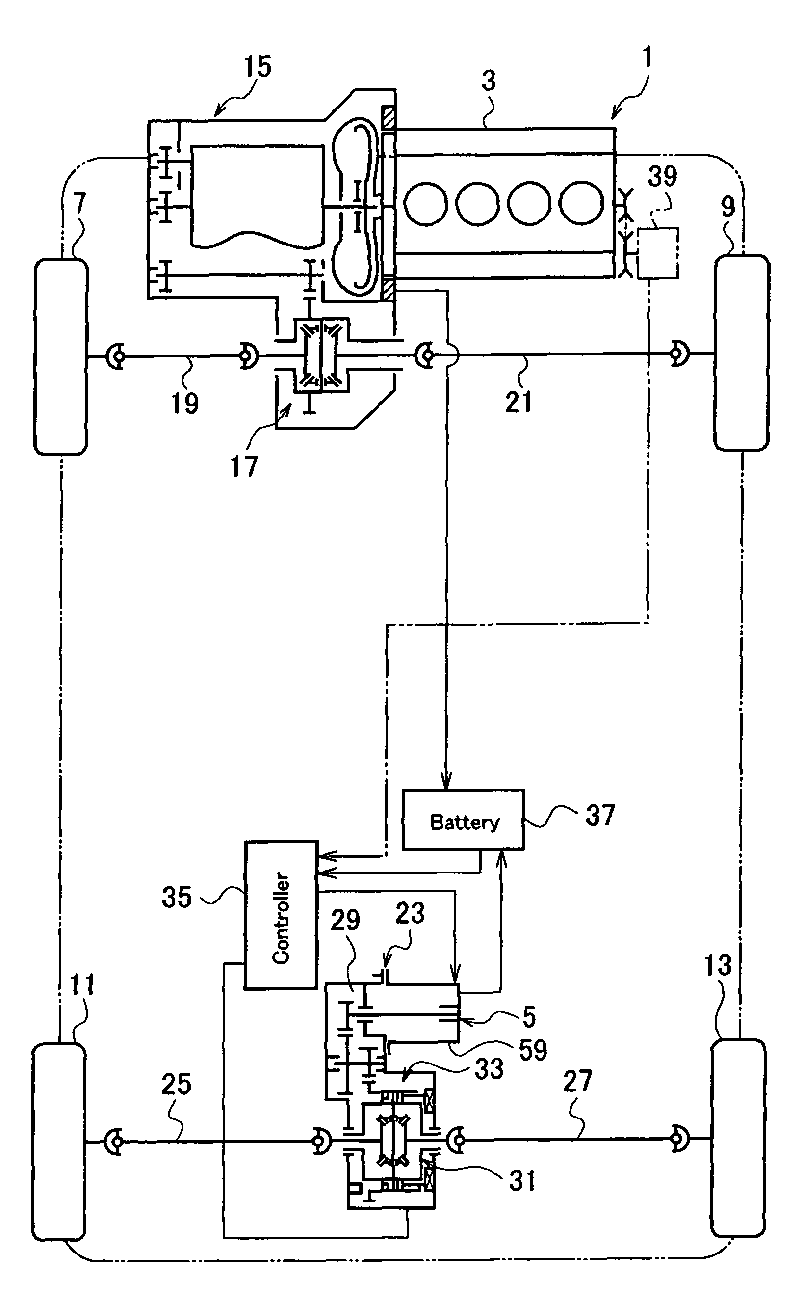
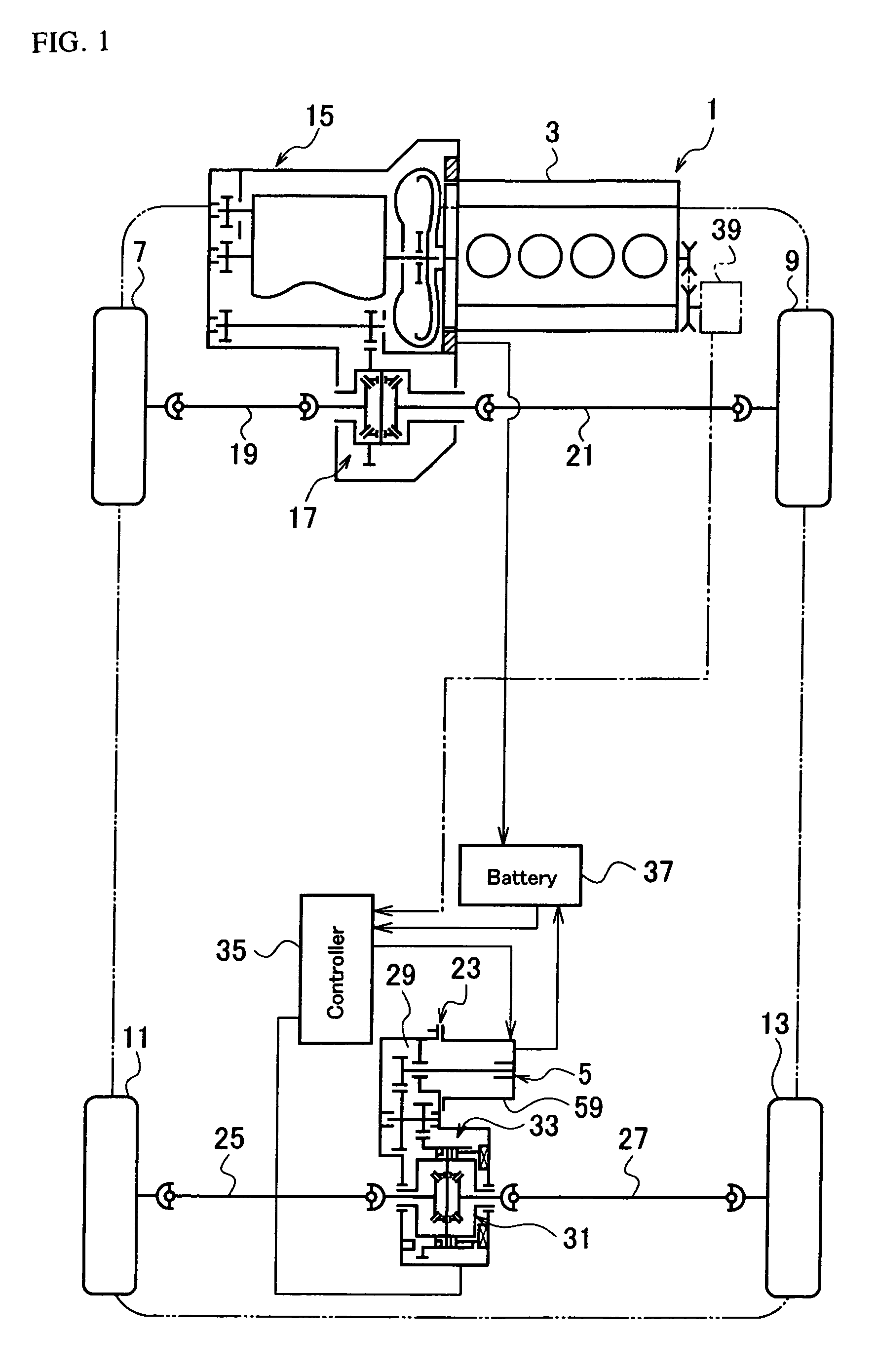
[0017]FIG. 1 is a skeleton plan view showing a four-wheel-drive vehicle employing a reduction drive device according to an embodiment of the present invention. As shown in FIG. 1, the four-wheel-drive vehicle 1 has an engine 3 that is an internal combustion engine serving as a main drive source and an electric motor 5 serving as a supplementary drive source.
[0018]The engine 3 is a main drive source for driving left and right front wheels 7 and 9 and the electric motor 5 is a supplementary drive source for driving left and right rear wheels 11 and 13. It is possible to configure so that the front wheels are driven by the supplementary drive source, i.e., the electric motor 5 and the rear wheels 11 and 13 by the main drive source, i.e., the engine 3.
[0019]Output of the engine 3 is supplied through a transmission 15 to a front differential 17. The front differential 17 is interlinked through left and right axle shafts 19 and 21 with the front wheels 7 and 9.
[0020]The electric motor 5 i...
embodiment 2
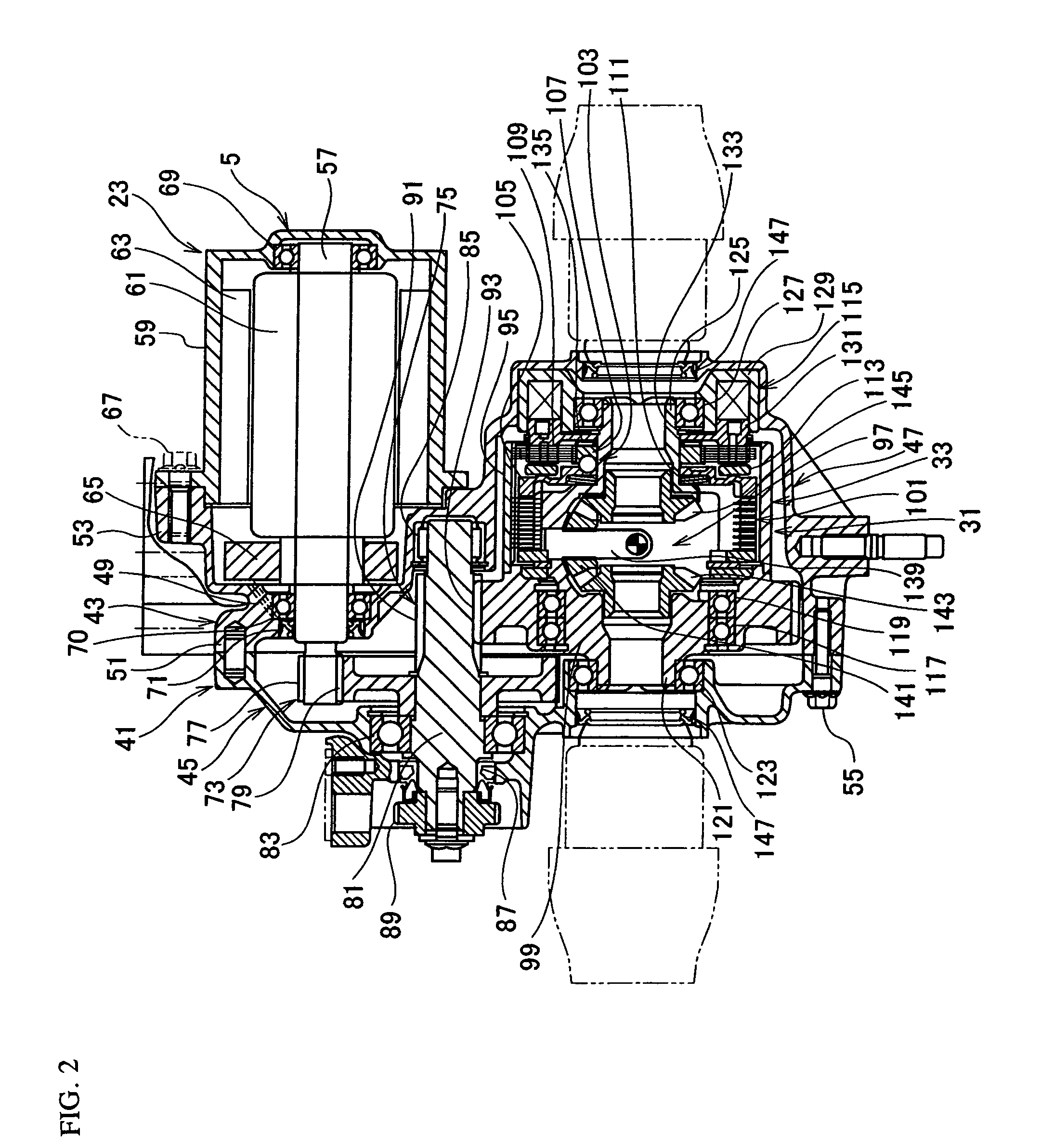
[0067]FIG. 3 is a sectional view showing a reduction drive device according to an embodiment 2 of the present invention. This embodiment is basically configured like the embodiment 1 of FIG. 2 and components corresponding to those of the embodiment 1 are explained with the use of the same reference marks or the same reference marks plus “A.”
[0068]According to the embodiment shown in FIG. 3, a rear differential 31A serving as a distribution mechanism is not provided with the clutch 33 of the embodiment 1 and a large gear 93A of a second reduction mechanism 75A is fixed to a differential case 95A with bolts 149.
[0069]Accordingly, this embodiment employs a slightly different torque transmission configuration. Through the large gear 93A of the second reduction mechanism 75A, torque is directly transmitted to the differential case 95A and the torque is distributed from the differential case 95A to left and right axle shafts 25 and 27 through a differential mechanism 97.
[0070]In addition,...
embodiment 3
[0074]FIG. 4 is a sectional view showing a reduction drive device according to an embodiment 3 of the present invention. This embodiment is basically configured like the embodiment 1 of FIG. 2 and components corresponding to those of the embodiment 1 are explained with the use of the same reference marks or the same reference marks plus “B.”
[0075]As shown in FIG. 4, the reduction drive device 23B has a first reduction mechanism 73B of modified structure, a second reduction mechanism 75B of modified arrangement, and a clutch 33B of modified structure, to uniquely arrange an electric motor 5B and a distribution mechanism.
[0076]The first reduction mechanism 73B of this embodiment consists of a planetary gear mechanism having a planetary carrier 151, planetary gears 153, an internal gear 155, and a sun gear 77B.
[0077]Left and right carrier plates 159 and 161 of the planetary carrier 151 support carrier pins 163. The carrier pins 163 are arranged in a circumferential direction of the pla...
PUM
 Abstract
Description
Claims
Application Information