
Synchronization of network nodes

a network node and synchronization technology, applied in the field of synchronizing clocks or references, can solve the problems of prohibitively high cost of many applications, add significantly to the cost of low-end applications, and high installation cost of antennas for these satellite signals, and achieve less accurate, accurate correction, and higher accuracy.

Active Publication Date: 2011-08-02
CIENA
View PDF17 Cites 22 Cited by
  • Summary
  • Abstract
  • Description
  • Claims
  • Application Information

AI Technical Summary

Benefits of technology

The patent describes a method for achieving high accuracy frequency synchronization between two clocks in a packet-carrying network. The method involves measuring a property of packet transmission between two nodes and comparing the measurements. The method allows for the use of a cheaper, less accurate oscillator, which can save costs and improve accuracy. The method can be used in applications like femtonodes and WiMax, where high accuracy synchronization is important. The invention also provides a way to measure the transfer delay between two routes and use it to simulate the behavior of different routes.

Problems solved by technology

Atomic references are some of the most stable references available today, but they are prohibitively expensive for many applications.
The Global Positioning System (GPS) and other navigational satellite systems can be used for these purposes, but still add significantly to the cost of low-end applications, and the antennas for these satellite signals are expensive to install, not always possible to site, and the signal is easily jammed.
Affordable local oscillators can exhibit significant frequency drift in use.
However the challenge with the physical layer method is that as the length of the distribution node and link chain increases, the frequency signal degrades as each successive node is traversed.
While the method is reasonably reliable, and has been used extensively in Synchronous Digital Hierarchy (SDH) networks, this has not been hitherto true of packet network nodes that do not rely on an SDH layer or that do not function as part of a transmission layer.
In particular, packet network physical links such as Ethernet do not perform to anywhere near similar accuracy as SDH.
However, the packet layer is not a constant communications channel, and it is highly susceptible to load variations at the packet switching nodes where varying amounts of traffic from varying numbers of source links desires to exit on one link.
This load variation gives rise to generally unpredictable statistics that causes packet arrival on any route between a master and slave to vary in its transfer delay (load induced packet jitter, or just load jitter) as well as potentially suffer lost packets when resources may overflow.
Even where a load profile may be constant and regular in time, packet size and rate, and within the capacity of all links on the route, packet switching nodes will still cause their own form of delay variation termed switching jitter.
In general this highly statistical and unpredictable behaviour of the packet layer can severely impair a clock signal, since any variation in delay across the network interferes with the instantaneous frequency rate and the information that can be extracted from the time distribution service packets.
The technique avoids the statistical impairment but suffers from the need to have a common high quality reference, which to date has relied on the communications network clock disseminated at the physical layer in SDH networks.
The challenge for this technique is that jitter induced by a load with high transient changes of small amplitude (level) are very difficult to discriminate from the general switching jitter (noise)—a non-stationary distribution, as well as a load that changes only very slowly i.e. over a long time; the former can radically change the delay through the network upsetting the phase of the PLL, and the latter becomes increasingly difficult to filter at ever lower frequencies, which ultimately result in a varying frequency offset in the slave.
All these techniques have to make the assumption that the delay in both directions of the route is equal, because there is a paradox that it is impossible to discern the delay in each direction separately without first synchronising the phase of the slave clock.
However this still does not make the phase of the slave clock knowable at the master because the delay to the slave receiving this instruction remains unknown.
Unfortunately, the delays of a packet network in different directions even for the same route are seldom equal, and for many networks the routes may differ in a physical sense in the directions master to slave and slave to master in terms of number of nodes, links and their distance.
Moreover, the delay over the route in either direction can vary considerably and independently as load in each direction varies in the network.
Elaborate algorithms are required to smooth out the packet switching jitter noise and variation of the distribution under load, but even constant loads will still cause constant phase offsets, and high transient loads can cause significant frequency offsets, or force the slave into a holdover mode that incurs its own drift by being decoupled from the master, by definition, at least for the duration of the disturbance.

Method used


Image

  • Synchronization of network nodes
  • Synchronization of network nodes
  • Synchronization of network nodes

Examples


first embodiment

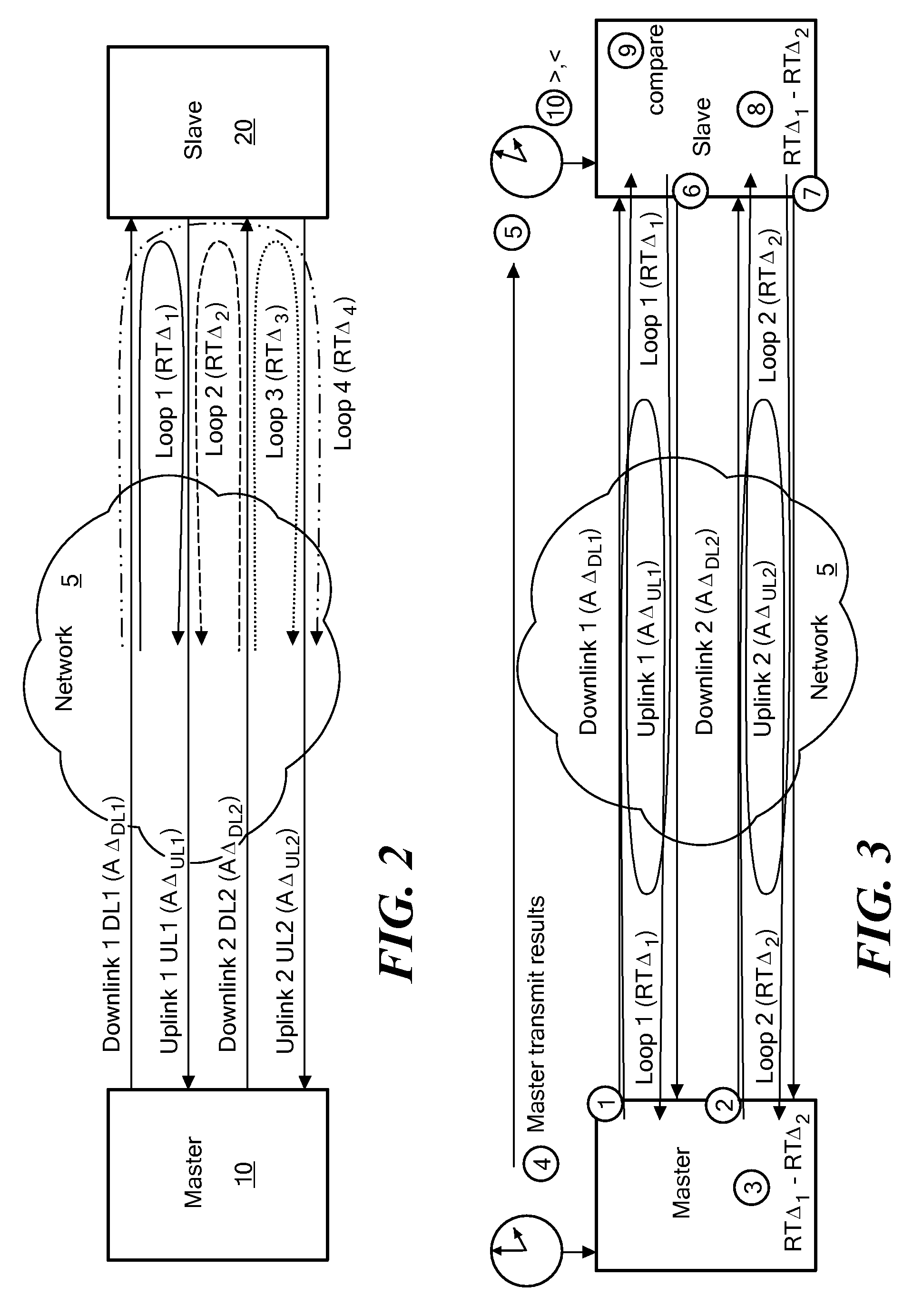
[0044]the method for measuring roundtrip transfer delay that is generally applicable to disjoint routes as well as routes with one direction in common will now be described with reference to FIG. 3.

Steps Performed at Master Node, 10

[0045](1) measure roundtrip transfer delay for a first route (e.g. Loop 1);[0046](2) measure roundtrip transfer delay for a second route (e.g. Loop 2, as defined in FIG. 3);[0047](3) determine difference value between the measurements obtained at step (1) and step (2);[0048](4) send the difference value calculated at step (3) to the slave node 20.

Steps Performed at Slave Node, 20[0049](5) receive difference value from Master node;[0050](6) measure roundtrip transfer delay for a first route (e.g. Loop 1);[0051](7) measure roundtrip transfer delay for a second route (e.g. Loop 2);[0052](8) determine difference value between the measurements obtained at step (6) and step (7);[0053](9) compare the difference calculated at step (8) and the difference value rec...

second embodiment

[0113]The second embodiment does not suffer at all from the effects of network oscillator drifts and much less to its variability. The preferred means of the slave measuring route downward transfer delay measurements can be effected with the same packets the master uses to measure route and inter-route roundtrip delays. This means that the network oscillator drifts and second order variability will be common to both the master and slave measurements of the downward direction. Furthermore the differences the master derives by using inter-route roundtrip measurements such as transfer delays, given the upward directions are by definition common measurements, any network oscillator drift is eliminated when the difference is calculated and any second order variability between packet arrivals from each respective downlink is tiny by comparison.

[0114]Finally, a balance is readily struck between the ppb differences of the master and slave clocks that are to be corrected, their drift during ...


PUM


Abstract

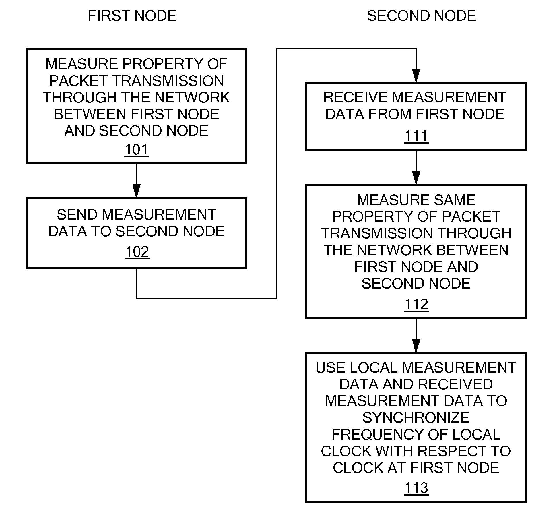
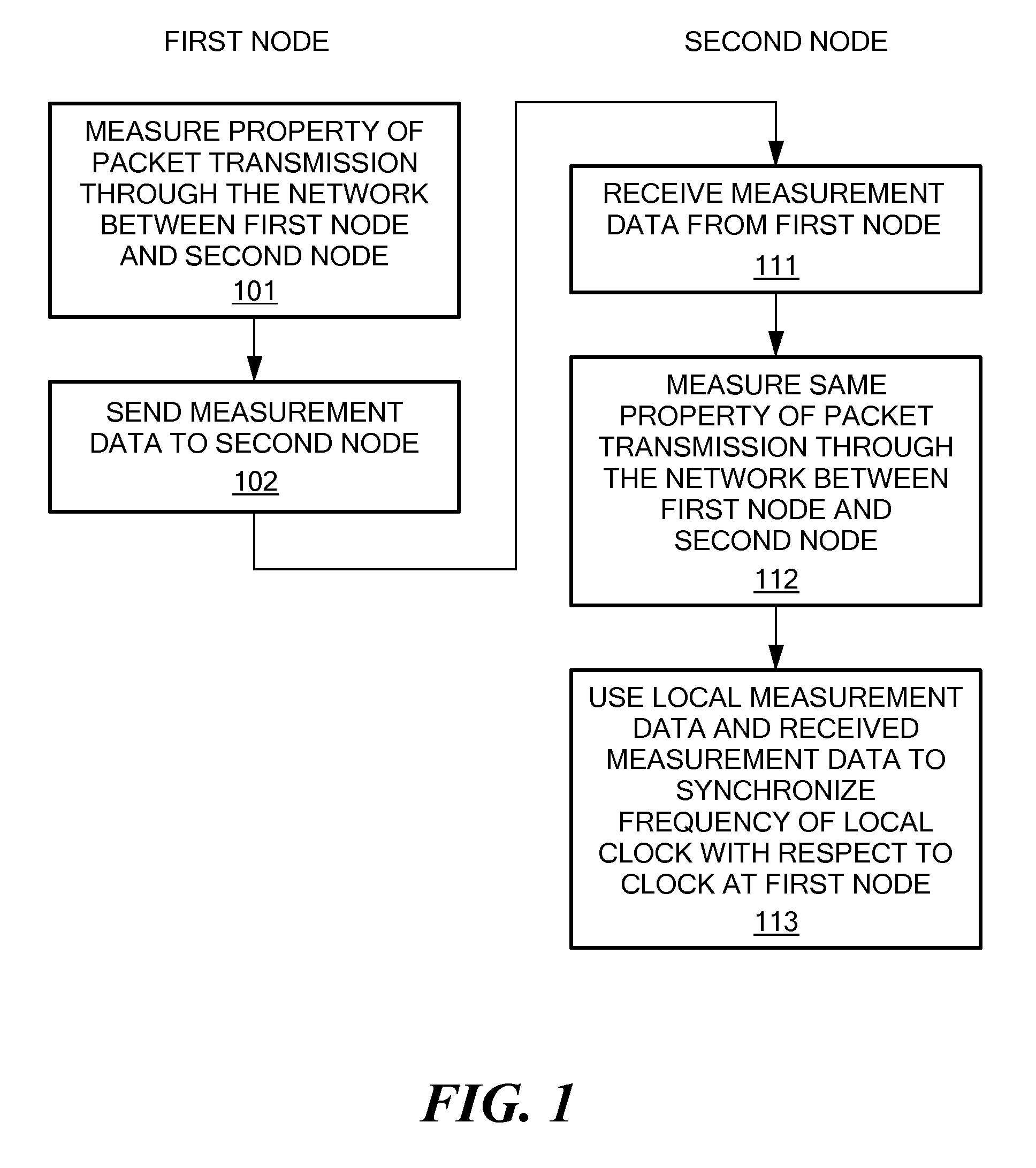
A method and apparatus are provided to achieve frequency synchronization between a first clock at a first node and a second clock at a second node of a packet-carrying communications network. At the first node: a property of packet transmission through the network between the first node and the second node is measured; and the measurement of the property is sent to the second node. At the second node, the same property of packet transmission through the network between the first node and the second node is measured. The measurement of the property made at the first node and the measurement of the property made at the second node are used to synchronize the frequency of the second clock with respect to the first clock.

Description

CROSS-REFERENCE TO RELATED APPLICATIONS[0001]This application is related to and claims priority to U.S. Provisional Patent Application No. 60 / 984,919, entitled SYNCHRONIZATION OF NETWORK NODES, filed Nov. 2, 2007, the entire contents of which are incorporated herein by reference.STATEMENT REGARDING FEDERALLY SPONSORED RESEARCH OR DEVELOPMENT[0002]n / aFIELD OF THE INVENTION[0003]This invention relates to synchronizing clocks or references at different nodes of a network.BACKGROUND OF THE INVENTION[0004]In many types of network there is often a need for a common frequency reference. A frequency reference may be used directly, or may be used to determine phase and time-of-day. In a communications network, one requirement for the frequency reference is to ensure that service buffers do not over or underflow, especially for long-lived information flows, and certain services also require phase control and time to various degrees of accuracy, which relies on the local availability of an acc...

Claims


Application Information

Patent Timeline
Patent Type & Authority Patents(United States)
IPC IPC(8): H04B7/212
CPCH04J3/0667
Inventor BRUECKHEIMER, SIMON DANIEL
Owner CIENA
Learn More