Medical viewing system and method for detecting boundary structures

a viewing system and boundary structure technology, applied in the field of medical viewing systems, can solve the problems of not easy to directly perform in noisy images, the doctor encounters a first very difficult step, and the most difficult tasks the doctor must perform, and achieve the effect of improving the visibility of the artery walls

Inactive Publication Date: 2011-08-02
KONINKLIJKE PHILIPS ELECTRONICS NV
View PDF9 Cites 17 Cited by
  • Summary
  • Abstract
  • Description
  • Claims
  • Application Information

AI Technical Summary

Benefits of technology

[0009]According to the invention, these problems are solved by an imaging system having means to process guide-wire tip information for determining the position of all the points of the skeleton of the guide-wire tip, and means to further register the region of interest around said position and means to enhance the visibility of the artery walls and guide wire in said region of interest. This system has means to display in real time the processed images during the angioplasty intervention for the doctor to correctly follow this intervention. This viewing system has processing means comprising tip detection means, registering means, enhancing means and zooming means that permit of accurately visualizing the guide wire with respect to the stenosed artery walls. It is also an object of the invention to provide such a system whose image processing means is user-actuatable.

Problems solved by technology

The first cited publication by Shirley A. M. Baert, is focused on guide-wire extraction based on rough estimation using template matching followed by optimization based on threadlike structure enhancement, which is not easy to directly perform in a noisy images.
However, before introduction of the stent, the doctor encounters a first very difficult step, which consists in passing the stenosis for the first time with the guide-wire.
This is one of the most difficult tasks the doctor must perform, because the passage the doctor has to steer through, which is the stenosed part of the artery, is very rough, irregular and limited.
When used, contrast agent must be introduced only in very small quantity during very small time duration because it presents toxicity for the patient.
The doctor must take advantage of this short moment to push the guide-wire forward, with the disadvantage that, due to the contrast agent, he does not see said guide-wire any more.
Indeed, this step of introducing the guide-wire for the first time is a very difficult step, due to the bad condition of imaging.
Not only are the guide-wire and the stenosed artery walls observed in noisy fluoroscopic images, but also they show low radiographic contrast that makes evaluation of the guide wire motion very difficult.
These movements make following the guide-wire introduction under fluoroscopic imaging still more difficult to perform.
Moreover, these movements make zooming inefficient because the object of interest may get out of the zoomed image frame.
The method of the first cited publication by Shirley A. M. Baert is of no help for localizing the guide-wire with respect to a stenosed part of the artery during the step of first introduction through said stenosed part, since this method estimates the position of the guide in world coordinates and does not provide means to suppress the drawback of the artery motion in the images.

Method used


Image

  • Medical viewing system and method for detecting boundary structures
  • Medical viewing system and method for detecting boundary structures
  • Medical viewing system and method for detecting boundary structures

Examples


Embodiment Construction

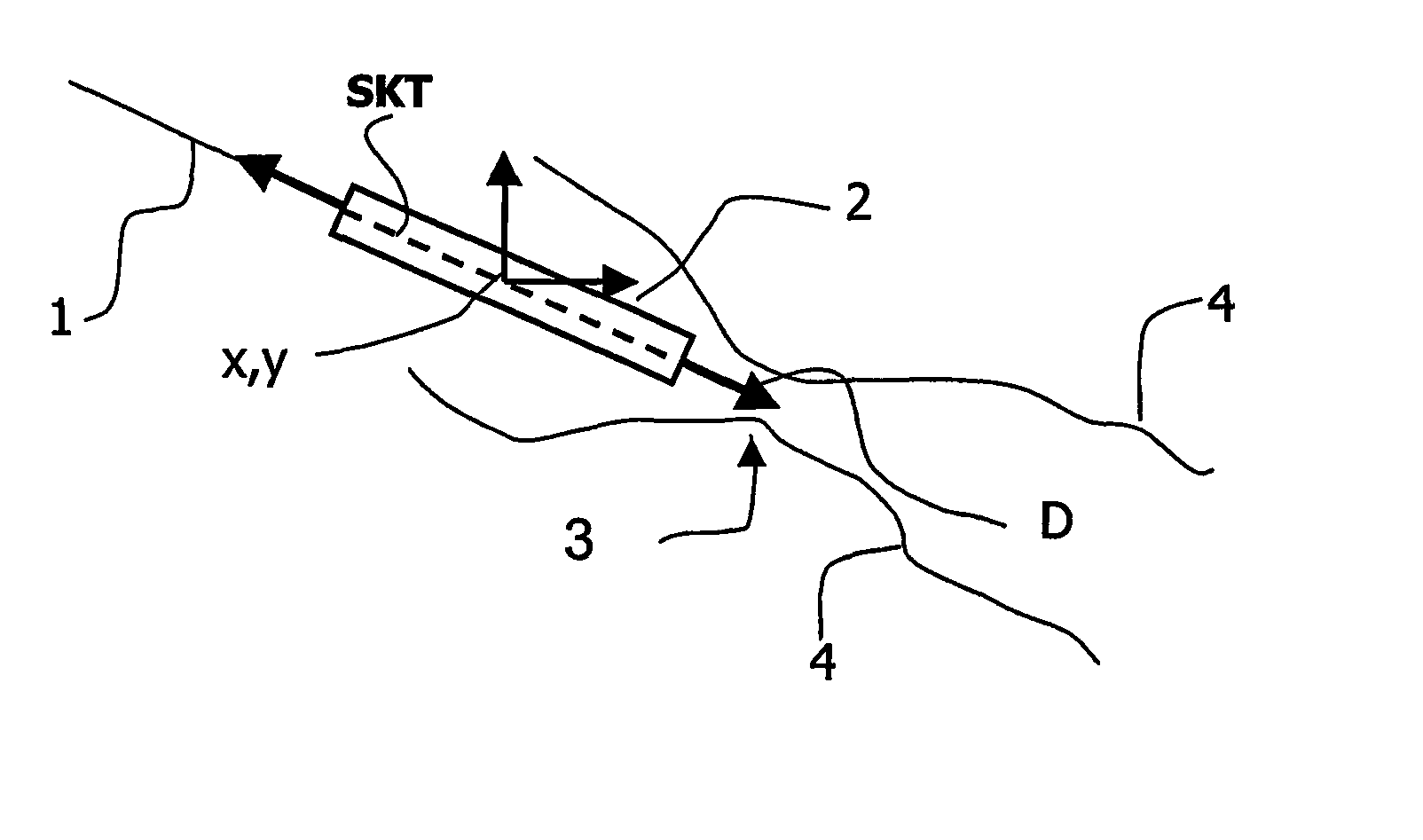
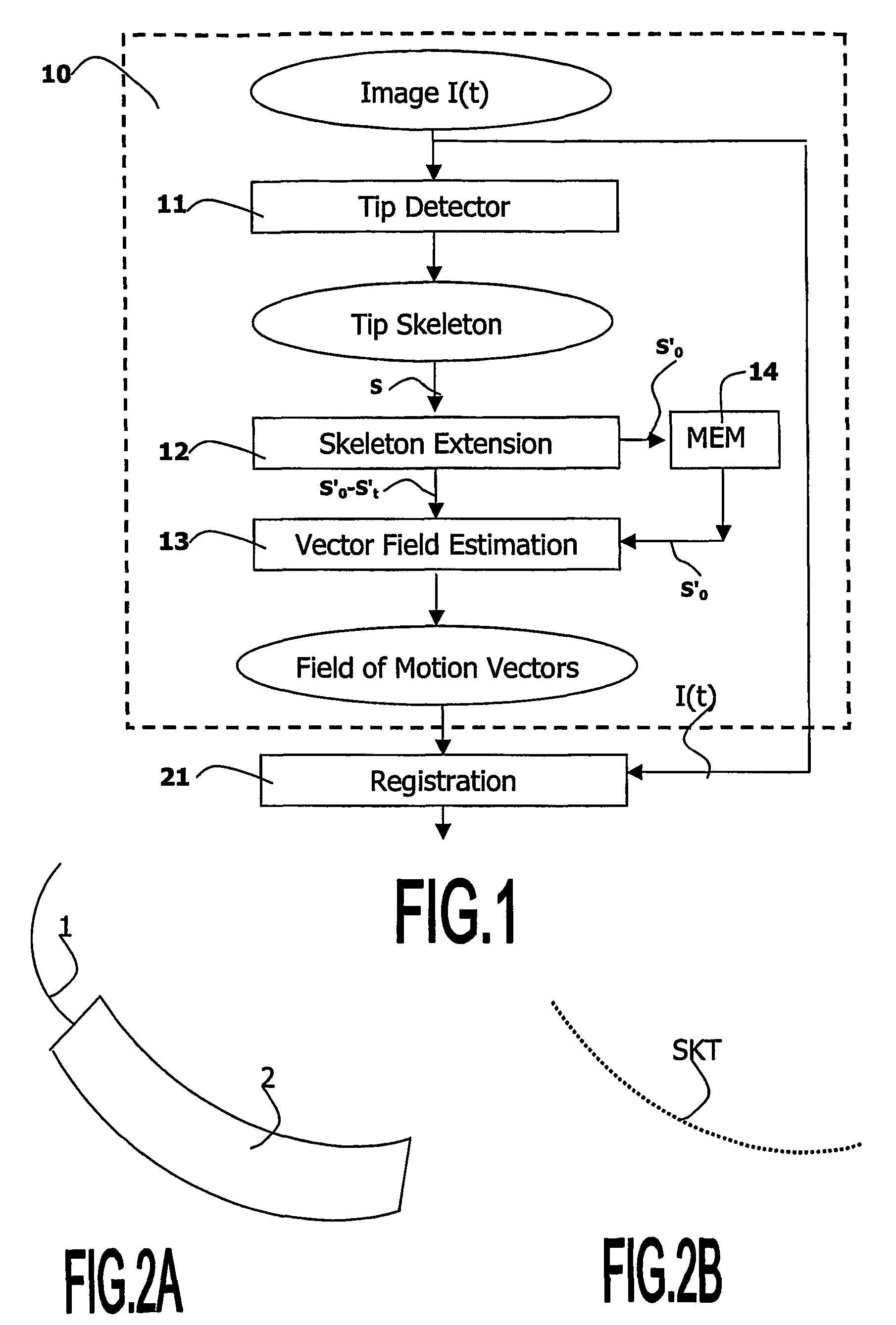
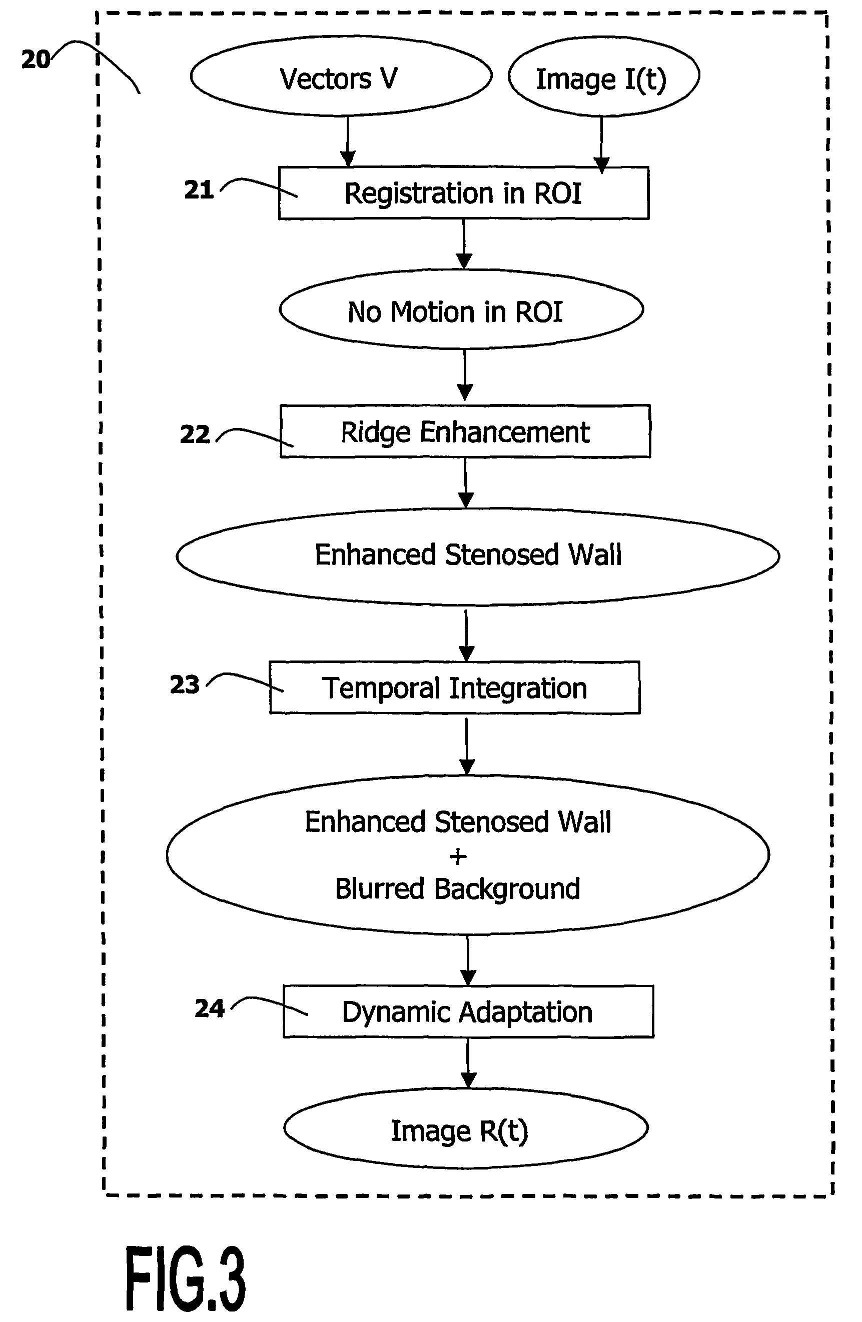
[0019]The invention relates to a viewing system, and to a computer executable image processing method that is used in the viewing system, for detecting, localizing, registering, enhancing and zooming structures in noisy images. The viewing system and the image processing method of the invention are described hereafter in an example of application to the medical field of cardiology. In said application, the object of interest is an artery, which is observed during a medical intervention called angioplasty, in a sequence of X-ray fluoroscopic images called angiograms.

[0020]Referring to FIG. 6A, the angioplasty is a medical intervention that usually comprises several stages for enlarging an artery at the location of a lesion called stenosis. In a preliminary stage, the practitioner localizes a stenosis 3 in a patient's artery 4 as best as possible in peri-interventional images. These images are obtained while using a contrast agent introduced in the artery in order to improve the image...


PUM


Abstract

A medical viewing system for displaying a sequence of medical images that represents moving and / or positioning a guide-wire in a blood vessel, which guide-wire has a guide-wire tip that is contrasted with respect to the guide wire, this system comprising acquisition means that acquires an original sequence of noisy images called live sequence and processing means for processing said live sequence of images in real time, the processing means comprising: first means (10) for automatically detecting the guide-wire tip, yielding skeleton information of the guide-wire tip and a field of motion vectors based on said skeleton information; second means (20) for automatically registering the guide-wire tip with respect to a reference based on the field of motion vectors and for enhancing the guide-wire and the vessel walls while blurring the background in the registered images; and comprising: Display means for displaying a live sequence of processed images.

Description

FIELD OF THE INVENTION[0001]The invention relates to a medical viewing system for displaying a sequence of images of a medical intervention that comprises moving and / or positioning a tool with respect to a body organ. The invention also relates to a computer executable image processing method to be used in said system. The invention further relates to a medical examination apparatus coupled to such a system. The invention finds for example its application in the medical field of cardiology, for registering and enhancing thin objects of interest such as vessel walls in arteriograms.BACKGROUND OF THE INVENTION[0002]A method to extract and track the position of a guide wire during endovascular interventions under x-ray fluoroscopy is already known from the publication entitled “2-D Guide wire tracking during endovascular interventions” by Shirley A. M. Baert, in “Medical Image Computing and Computer-Assisted Intervention”—MICCAI 2000, S. L. Delp, A. M. DiGioia, B. Jaramaz (eds), vol. 1...

Claims


Application Information

Patent Timeline
Patent Type & Authority Patents(United States)
IPC IPC(8): A61B6/12A61B6/00A61B17/22A61B19/00G06T5/50G06T7/00
CPCA61B6/481A61B6/504A61B19/52A61B19/5244G06T5/50G06T7/0038A61B6/12A61B17/22A61B2017/22042A61B2019/5238A61B2019/5265G06T2207/10121G06T2207/30021G06T2207/30101A61B90/36A61B34/20A61B2090/376A61B2034/2065G06T7/38
Inventor FLORENT, RAOULNOSJEAN, LUCILELELONG, PIERRE
Owner KONINKLIJKE PHILIPS ELECTRONICS NV
Why Eureka
Try Eureka