Feedback control scheme for optimizing dewatering processes

a control scheme and dewatering technology, applied in the field of dewatering effluents, can solve the problems of increasing the amount of thermal drying required, putting in ways, and requiring a large amount of effor

Inactive Publication Date: 2011-08-09
DUNBAR JAMES M
View PDF12 Cites 1 Cited by
  • Summary
  • Abstract
  • Description
  • Claims
  • Application Information

AI Technical Summary

Problems solved by technology

Accordingly, a large amount of effort has, in recent years, been put into ways of optimizing drainage and dewatering.
A disadvantage of drainage aids is that they tend to increase the amount of thermal drying that is required.
In other words, they accelerate the free drainage but they result in the wet sheet containing a larger amount of trapped water, and so additional thermal drying is required.
While such schemes improved filtrate clarity which facilitated sludge drainage thus maximizing final cake dryness, over-drying of the sludge created press plugging and equipment damage.
Removal of the sludge results in a clarified water byproduct having a certain measurable turbidity.
However, such manual operation is inherently problematic due to the variation in incoming gray water properties coupled with operating variables which necessitate variations in optimum polymer flow required to deliver the optimum filtrate clarity.
Such conservatism ultimately results in lost throughput potential and reduced dewatering capabilities.
Known control systems which depend on detecting changes in filtrate turbidity do not allow for the fact that turbidity changes can occur for a number of reasons.
These normal variations in operating conditions lead to significant variations in the filtrate turbidity.
A disadvantage of existing control systems is that, as the various sludge properties change, the required polymer feed rate to achieve optimum clarity requires change.
To date, such solutions have not yielded optimum performance.

Method used


Image

  • Feedback control scheme for optimizing dewatering processes
  • Feedback control scheme for optimizing dewatering processes
  • Feedback control scheme for optimizing dewatering processes

Examples


first embodiment

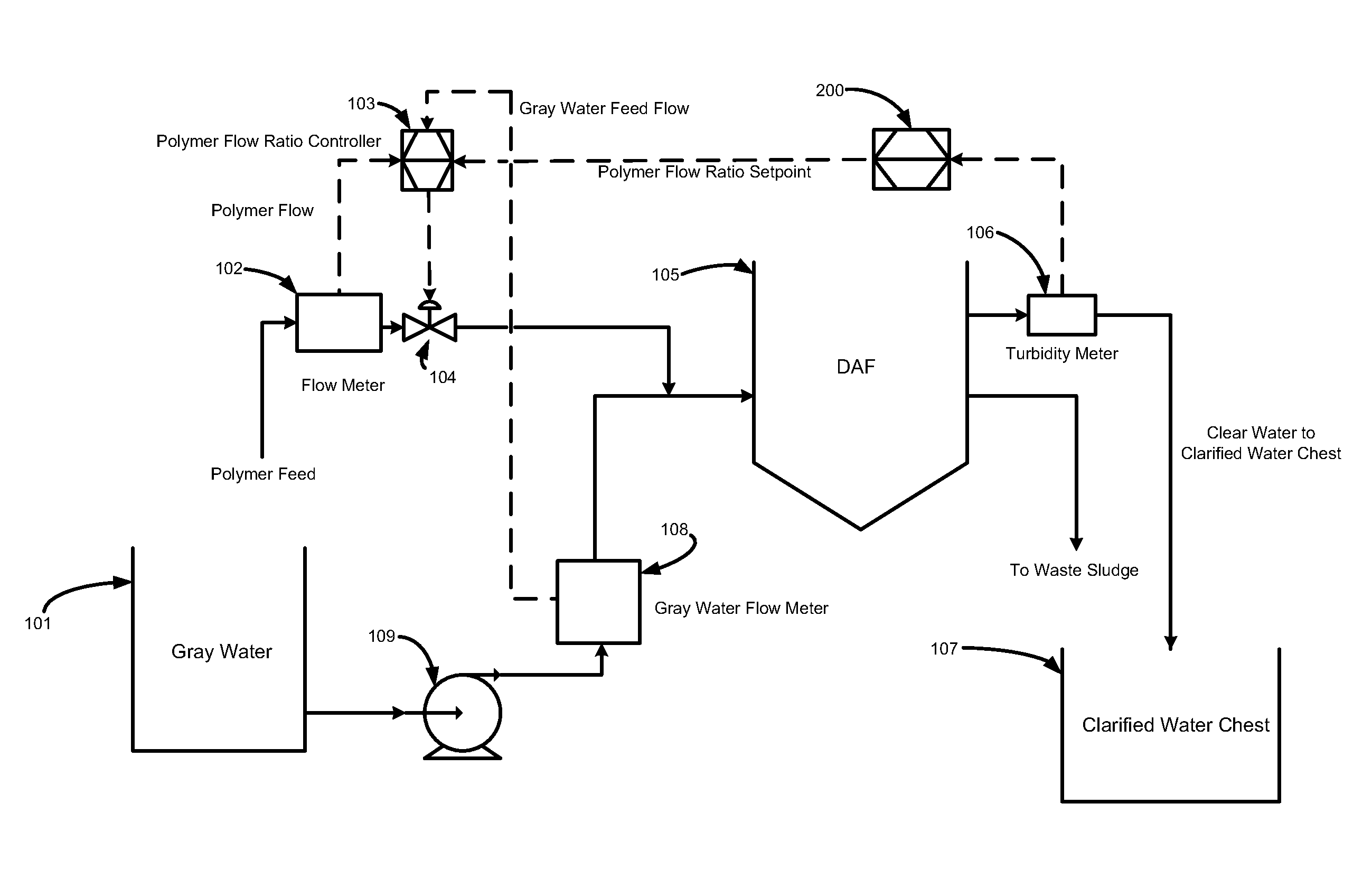
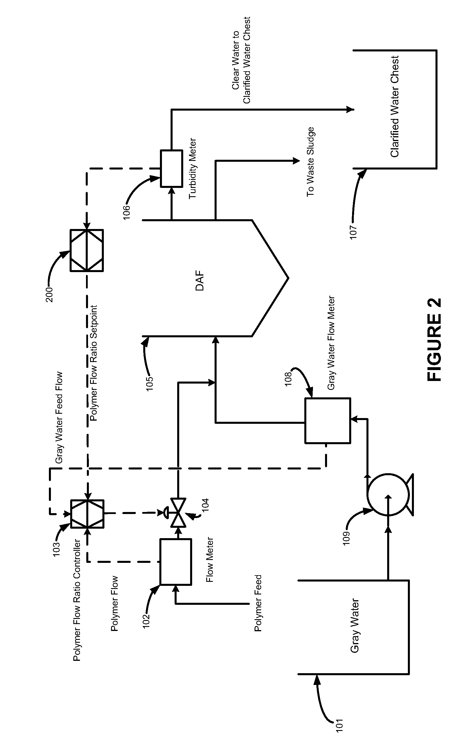
[0038]FIG. 2 shows a simplified schematic of the present inventive apparatus implemented within a dewatering process involving dissolved air flotation. As the basic physical architecture within FIG. 2 is substantially similar to prior art FIG. 1, like numerals are used for like elements.

[0039]As before, gray water is supplied to a tank 101 as effluent from some known industrial process (not shown). A pump 109 moves the gray water through a line to a diffused air flotation device (DAF) 105. A flow meter 108 typically resides in the line between the pump 109 and DAF 105 in order to provide information on the rate of gray water flow to the DAF 105. This information is used by a controller 103 that controls the flow ratio of polymer additive relative to gray water. To that end, another flow meter 102 is provided in the polymer feed line so as to provide polymer flow information to the controller 103. As a product of the flocculation within the DAF 105, waste sludge is separated from the...

second embodiment

[0056]Sludge dewatering as an implementation of the present invention is shown by way of FIG. 5 which is a simplified schematic of the present inventive apparatus implemented within a dewatering process involving a sludge press device. Again, while specific measurements and settings are used as turbidity thresholds, delays, and polymer adjustment increments, it should be readily understood that all such measurements and settings may vary in accordance with the given industrial application using the inventive methodology without straying from the intended scope of the present invention. Therefore, it should be understood that such measurements and settings as discussed herein below are illustrative of the present embodiments with regard to a sludge press device and should not be considered limiting in terms of the instant invention.

[0057]In general, the sludge dewatering system shown in FIG. 5 functions by configuring an amperage control scheme that controls the press feed rate by co...


PUM

PropertyMeasurementUnit
volumeaaaaaaaaaa
turbidityaaaaaaaaaa
smoothnessaaaaaaaaaa

Abstract

A method and apparatus for dewatering of effluents through the use of automated optimization using feedback control. The method and apparatus for feedback control optimizes dewatering processes for any water cleansing process that uses retention and / or flocculation aids (e.g., polymers) to impact endpoint water clarity. Disclosed implementations include processing using dissolved air flotation (DAF) and sludge cake formation. The methodology includes real-time monitoring of turbidity and incremental control of polymer to manage changes to turbidity / suspended solids due to operating parameters such as temperature, chemical variations, and mechanical influences.

Description

[0001]This application claims benefit of U.S. Provisional Patent Application Ser. No. 61 / 044,129, filed 11 Apr. 2008, which is incorporated herein by reference in its entirety.FIELD OF THE INVENTION[0002]The present invention relates generally to dewatering of effluents. More particularly, the present invention relates to an automated optimization method and apparatus providing feedback control to enhance dewatering processes.BACKGROUND OF THE INVENTION[0003]Within the papermaking industry, paper or paper board is made by forming an aqueous cellulosic suspension (usually known as a thin stock or paper slurry in general), draining the suspension to form a sheet, and drying the sheet. The draining and drying stages are designed such that the sheet has the desired properties for the final paper or paper board and so generally involves surface treatments to impart adequate smoothness and other performance properties to the sheet. In papermaking, such treatments may involve calendaring f...

Claims


Application Information

Patent Timeline
Patent Type & Authority Patents(United States)
IPC IPC(8): C02F1/24C02F1/56C02F11/14C02F11/121C02F11/147
CPCC02F1/008C02F1/5209D21C9/18D21H21/10C02F1/24C02F1/56C02F11/121C02F11/14C02F2103/002C02F2209/001C02F2209/003C02F2209/006C02F2209/11C02F2209/40Y10S210/928C02F11/147
Inventor DUNBAR, JAMES M.
Owner DUNBAR JAMES M
Why Eureka
Try Eureka