
Transfer substrate, and fabrication process of organic electroluminescent devices

a technology of organic electroluminescent devices and transfer substrates, which is applied in the direction of diffusion transfer processes, photosensitive materials, instruments, etc., can solve the problems of reduced luminescence efficiency, reduced brightness half-life, and increased drive voltage, and achieves the effect of facilitating the formation of the transfer substrate 100′

Inactive Publication Date: 2011-08-09
JOLED INC
View PDF16 Cites 5 Cited by
  • Summary
  • Abstract
  • Description
  • Claims
  • Application Information

AI Technical Summary

Benefits of technology

This approach enables reliable pattern formation of the light emitting layer, enhancing luminescence efficiency, reducing drive voltage, and extending the brightness half-life of organic electroluminescent devices.

Problems solved by technology

The heat transfer process, therefore, involves problems of a reduced luminescence efficiency, an increased drive voltage, a reduced brightness half-life and the like due to the failure in surely forming a hole transport layer in a pattern.

Method used


Image

  • Transfer substrate, and fabrication process of organic electroluminescent devices
  • Transfer substrate, and fabrication process of organic electroluminescent devices
  • Transfer substrate, and fabrication process of organic electroluminescent devices

Examples


first embodiment

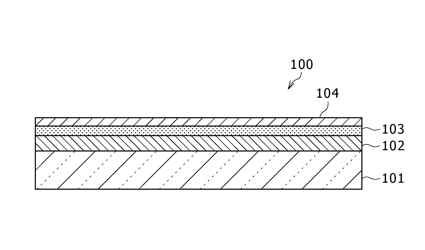
[0029]Referring first to FIG. 1, a description will hereinafter be made of the construction of a transfer substrate 100 according to the first embodiment of the present invention. The transfer substrate 100 depicted in the figure is useful, for example, for the formation of a hole transport layer in an organic electroluminescence device, and is composed of a photothermal conversion layer 102, an antioxidation layer 103 and a transfer layer 104 formed in this order on a base substrate 101.

[0030]Of these, the base substrate 101 is made of a material which transmits light hr of a predetermined wavelength to be irradiated in a transfer to be performed using the transfer substrate 100. When a laser beam of approx. 800 nm wavelength from a solid-state laser source is employed as this light hr, for example, a glass substrate may be used as the base substrate 101.

[0031]The photothermal conversion layer 102 is formed using a material, which has a high photothermal conversion efficiency in co...

second embodiment

[0085]FIG. 4 is a cross-sectional construction diagram of a transfer substrate 100′ for use in this embodiment. It is to be noted that like elements of structure to those in the first embodiment will be described by applying like reference numerals. As depicted in this figure, the transfer substrate 100′ is constructed by successively stacking a photothermal conversion layer 102, an antioxidant layer 103 and a transfer layer 104′ on a base substrate 101.

[0086]In this embodiment, the transfer layer 104′ is formed by stacking at least three organic material layers one over another. Described specifically, the transfer 104′ layer is constructed by successively stacking a first layer 104a′, a second layer 104b′ and a third layer 104c′ from the side of the base substrate 101.

[0087]The first layer 104a′ on the side of the base substrate 101 and the third layer 104c′ on the side of the surface are each formed with an organic material selected from the group including a first organic materi...

examples

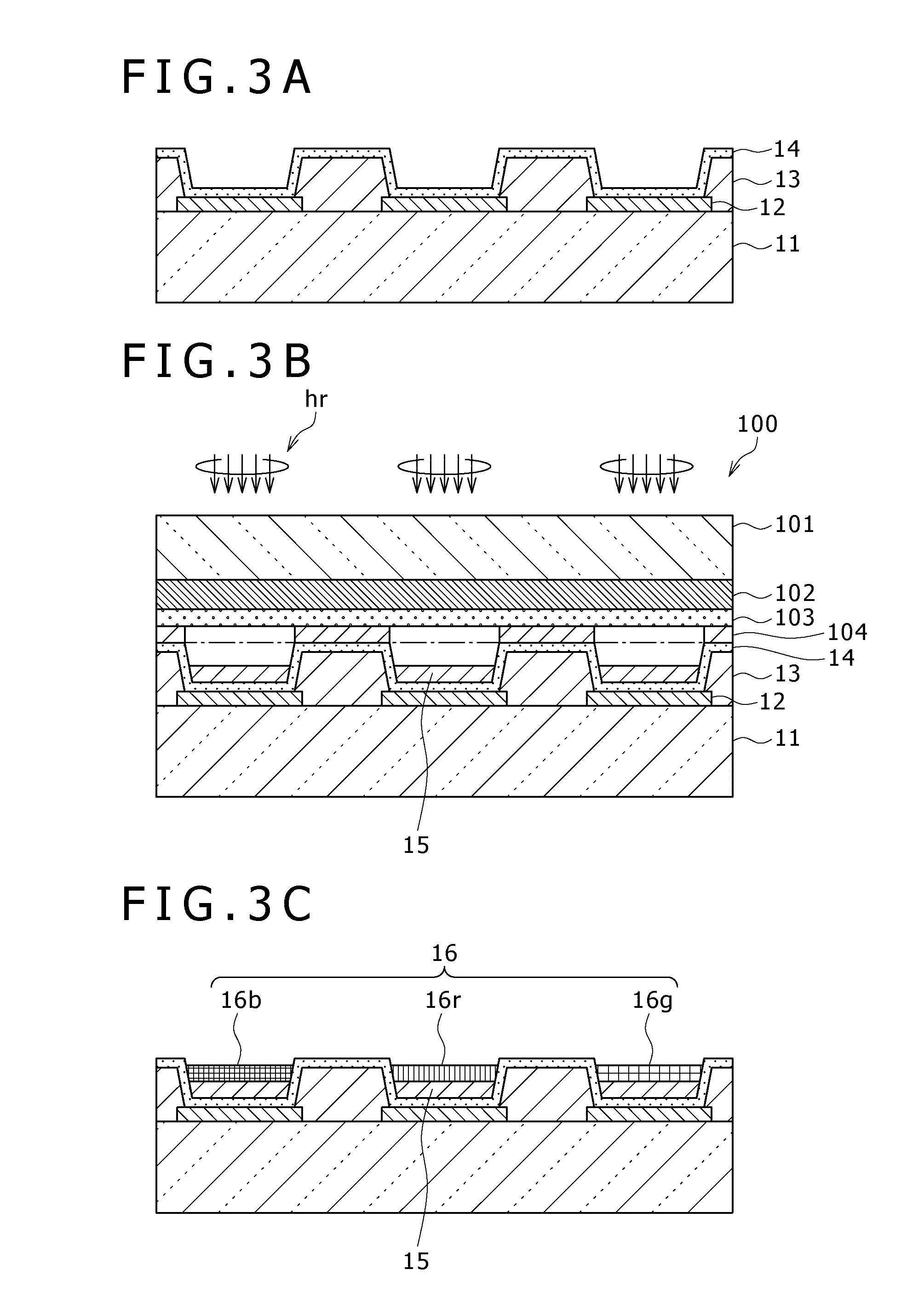
[0097]A description will next be made of fabrication procedures of organic electroluminescent devices of specific examples of the present invention and comparative examples to these specific examples and also of their evaluation results.


PUM

PropertyMeasurementUnit
temperatureaaaaaaaaaa
Tmaaaaaaaaaa
wavelengthaaaaaaaaaa

Abstract

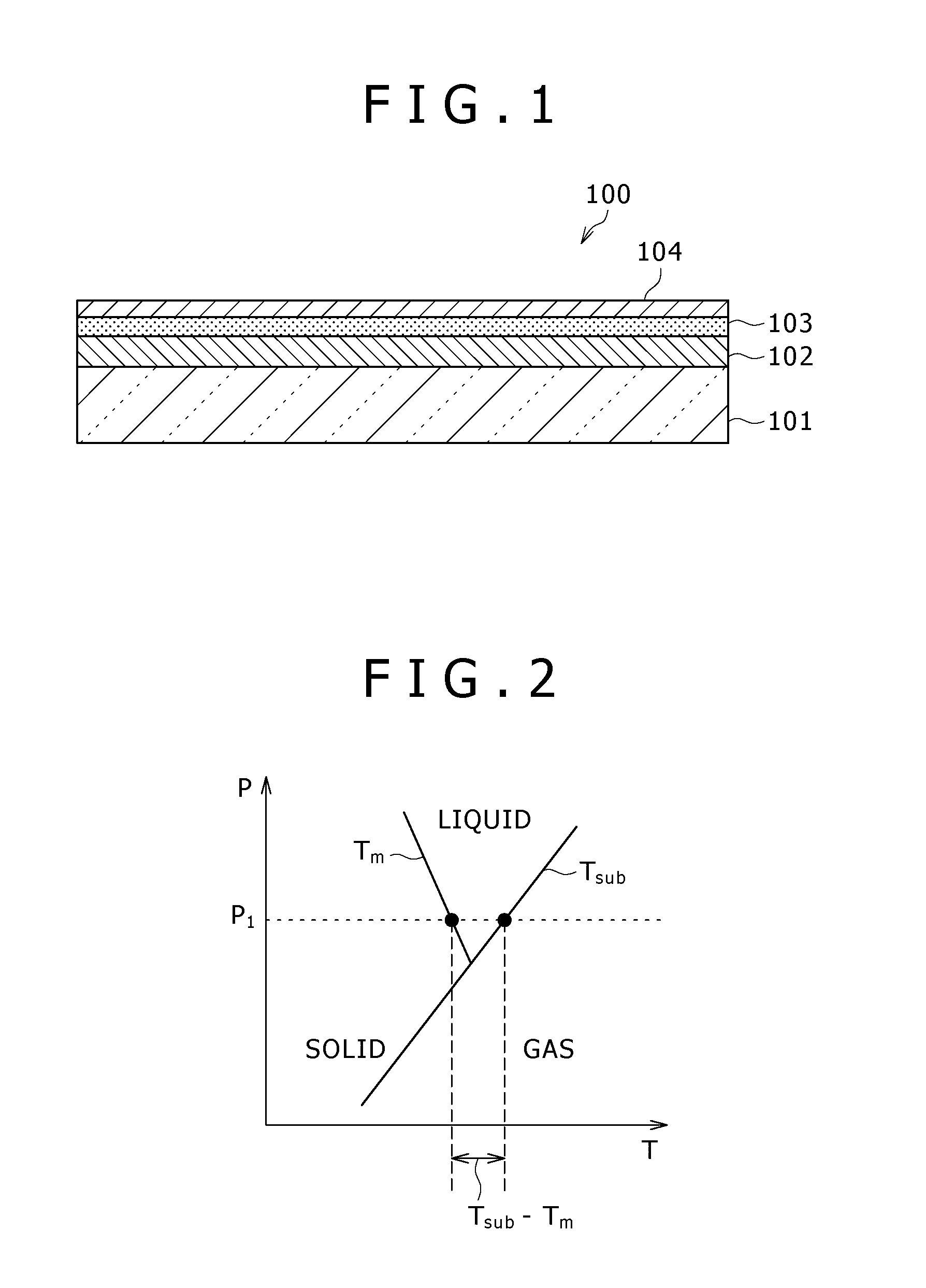
A transfer substrate is provided with a photothermal conversion layer and a transfer layer formed in this order on a base substrate. The transfer layer is formed of an organic material selected from the group including a first organic material, which has a weight decrease initiation temperature (Tsub) of lower than 500° C. and sublimates under atmospheric pressure, and a second organic material, which has a weight decrease initiation temperature (Tsub) of lower than 500° C. and satisfies the following inequality: Tsub−Tm<200° C. (Tsub: the weight decrease initiation temperature of the second organic material, and Tm: a melting point of the second organic material). Also disclosed is a process for fabricating organic electroluminescent devices by using the transfer substrate.

Description

CROSS REFERENCES TO RELATED APPLICATIONS[0001]The present invention contains subject matter related to Japanese Patent Application JP 2007-096271 filed in the Japan Patent Office on Apr. 2, 2007, the entire contents of which being incorporated herein by reference.BACKGROUND OF THE INVENTION[0002]1. Field of the Invention[0003]This invention relates to a transfer substrate and a fabrication process of organic electroluminescent devices, and especially to a transfer substrate useful in the transfer of a hole-transporting material and a process for fabricating organic electroluminescent devices by using the transfer substrate.[0004]2. Description of the Related Art[0005]Organic electroluminescent devices making use of electroluminescence of organic materials are each formed by arranging an organic layer, which is composed of a hole transport layer and a light emitting layer stacked together, between a lower electrode and an upper electrode, and are attracting interests as light emittin...

Claims


Application Information

Patent Timeline
Patent Type & Authority Patents(United States)
IPC IPC(8): G03F7/00B41M5/025
CPCH01L51/0013Y02E10/549C23C14/048Y10T428/31504H10K71/18H05B33/10H10K71/00
Inventor TAKAGI, RYOKOMATSUNAMI, SHIGEYUKIKIJIMA, YASUNORI
Owner JOLED INC
Learn More