Semiconductor device

a technology of semiconductor substrate and barrier film, which is applied in the direction of mechanical actuation of burglar alarms, protective material radiating elements, instruments, etc., can solve the problems of contaminated semiconductor elements, hardly improved reliability of id chips, and lower mechanical strength of semiconductor substrates than those of above magnetic cards and bar codes, so as to suppress stress per sheet of barrier films, and increase the thickness of barrier films

Inactive Publication Date: 2011-08-09
SEMICON ENERGY LAB CO LTD
View PDF25 Cites 22 Cited by
  • Summary
  • Abstract
  • Description
  • Claims
  • Application Information

AI Technical Summary

Benefits of technology

[0007]In view of the above problems in the conventional art, the present invention has an object to provide a semiconductor device which is capable of increasing the reliability of a semiconductor element and improving the mechanical strength without suppressing the scale of a circuit.
[0020]Furthermore, the ID chip according to the invention comprises advantages as follows. Since the integrated circuit is formed using the electrically-isolated TFT in the ID chip of the invention, a parasitic diode is hardly formed between the integrated circuit and the substrate, unlike a transistor formed over a semiconductor substrate. Therefore, a large amount of current does not flow through a drain region due to a potential of an alternating-current signal that is applied to a source or a drain region, which hardly causes the deterioration or failure. As compared with an ID chip using a semiconductor substrate, radio waves are hardly blocked in the ID chip of the invention so that a signal can be prevented from being attenuated due to blocking of the radio waves.

Problems solved by technology

However, it is assumed that the semiconductor element is contaminated with alkali metal such as Na, alkali earth metal and moisture, depending on the environment to be used with the ID chip.
When the alkali metal, the alkali earth metal or moisture is dispersed in a semiconductor film used in the semiconductor element, the characteristics of the semiconductor element are deteriorated, and therefore, the reliability of the ID chip is hardly improved.
However, a semiconductor substrate has lower mechanical strength than those of the above magnetic card and bar code.
When the ID chip is formed over a packing material, a certificate, a bank note, a portfolio and the like, each of which uses a flexible material as its support medium, there is a probability that the ID chip is damaged in use.
Therefore, the ID chip has been not feasible.
In this case, however, a circuit with the adequate scale is hardly ensured, which results in limitation in the application of the ID chip.
Meanwhile, when it is emphasized that the enough scale of the circuit is ensured, the dimension of the ID chip cannot be reduced randomly so that the improvement of the mechanical strength is limited.
Accordingly, there is a drawback in which signals are easily attenuated depending on the direction of transmitting the radio waves.

Method used


Image

  • Semiconductor device
  • Semiconductor device
  • Semiconductor device

Examples


embodiment 1

[0109]In the embodiment, a method for manufacturing an ID chip in which an antenna and an integrated circuit that are formed over different substrates are electrically connected to each other will be described, differing from FIGS. 2A to 2D, FIGS. 3A to 3C, and FIGS. 4A and 4B.

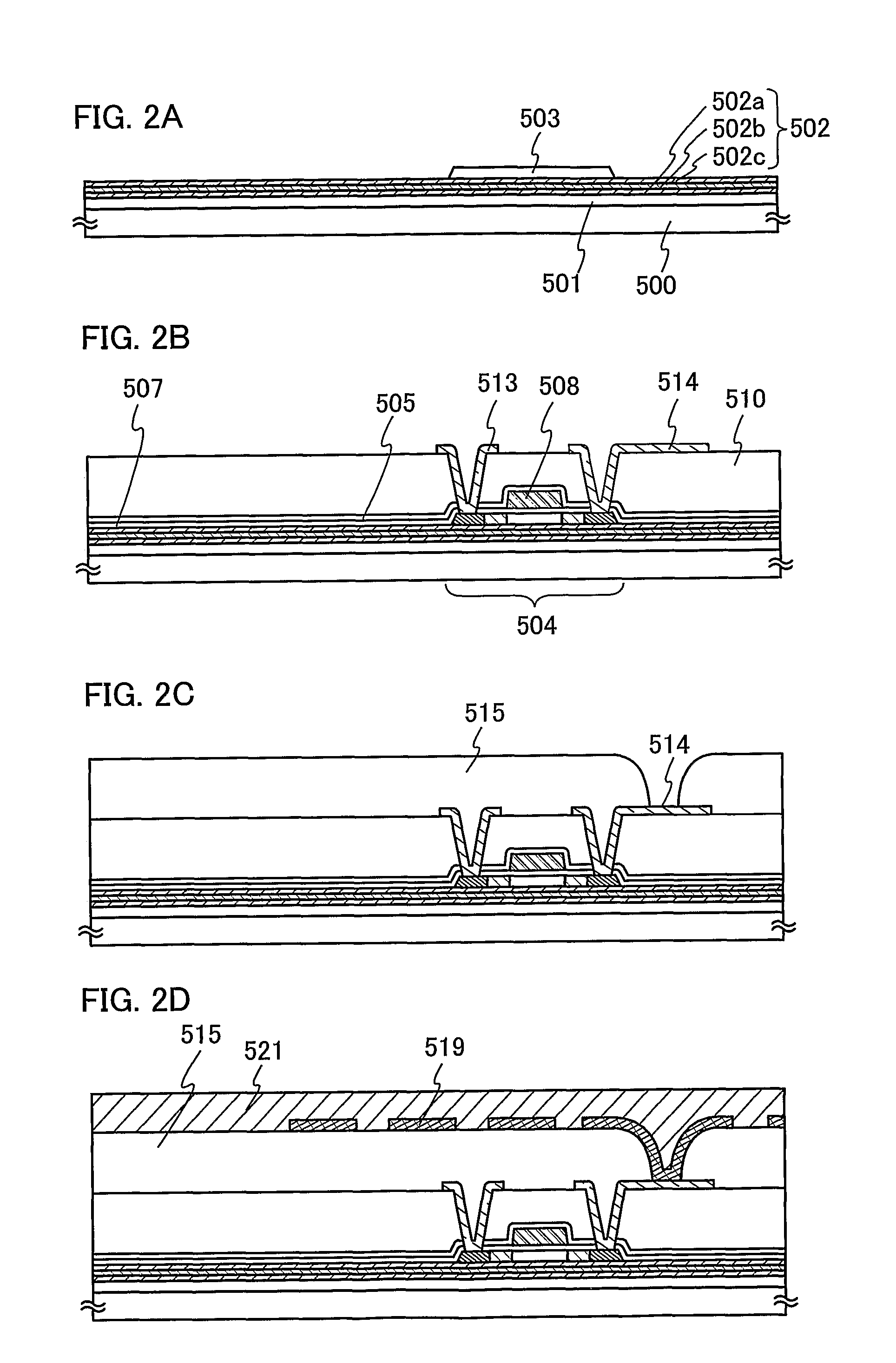
[0110]After forming the second interlayer insulating film 515 with an opening as shown in FIG. 2C, a wiring 550 connected to the wiring 514 is formed so as to be in contact with the second interlayer insulating film 515 as shown in FIG. 5A. A protective layer 551 is formed over the second interlayer insulating film 515 so as to cover the wiring 550. The structure and the manufacturing method of the protective layer 551 can refer the descriptions with respect to the protective layer 521 as shown in FIG. 2D.

[0111]A groove 552 is next formed to separate the ID chips one another. As shown in FIG. 5B, the separation layer 501 is removed by etching. The specific method for forming the groove 552 and the concrete met...

embodiment 2

[0123]A structure of an ID chip in the case of forming a wiring connected to a TFT and an antenna by patterning one conductive film will be explained. FIG. 6A is a cross sectional view of the ID chip according to the present embodiment.

[0124]In FIG. 6A, reference numeral 601 denotes a TFT. The TFT 601 includes a semiconductor film 602, a gate insulating film 603 for covering the semiconductor film 602 and a gate electrode 604 that overlaps with the semiconductor film 602 while sandwiching the gate insulating film 603 therebetween. The TFT 601 is covered with a passivation film 605 and a first interlayer insulating film 606. A wiring 607 formed on the first interlayer insulating film 606 is connected to the semiconductor film 602 via the gate insulating film 603, the passivation film 605 and the first interlayer insulating film 606.

[0125]An antenna 608 is formed on the first interlayer insulating film 606. The wiring 607 and the antenna 608 can be made together by forming a conductiv...

embodiment 3

[0126]A structure of an ID chip in the case of forming a gate electrode of a TFT along with an antenna by patterning one conductive film will be explained in the embodiment. FIG. 6B is a cross sectional view of the ID chip according to the present embodiment.

[0127]In FIG. 6B, reference numeral 611 denotes a TFT. The TFT 611 includes a semiconductor film 612, a gate insulating film 613 covering the semiconductor film 612 and a gate electrode 614 that overlaps with the semiconductor film 612 while sandwiching the gate insulating film 613 therebetween. An antenna 618 is formed on the gate insulating film 613. The gate electrode 614 and the antenna 618 can be made together by forming a conductive film on the gate insulating film 613 and patterning the conductive film into the respective patterns. By forming the antenna 618 and the gate electrode 614 together, the number of steps for manufacturing the ID chip can be reduced.


PUM


Abstract

An object of the present invention is providing a semiconductor device that is capable of improving the reliability of a semiconductor element and enhancing the mechanical strength without suppressing the scale of a circuit. The semiconductor device includes an integrated circuit sandwiched between first and second sealing films, an antenna electrically connected to the integrated circuit, the first sealing film sandwiched between a substrate and the integrated circuit, which includes a plurality of first insulating films and at least one second insulating film sandwiched therebetween, the second sealing film including a plurality of third insulating films and at least one fourth insulating film sandwiched therebetween. The second insulating film has lower stress than the first insulting film and the fourth insulating film has lower stress than the third insulating film. The first and third insulating films are inorganic insulating films.

Description

TECHNICAL FIELD[0001]The present invention relates to a semiconductor device which is capable of communicating via radio waves.BACKGROUND ART[0002]A semiconductor device typified by an ID chip, which can send and receive data such as identification information by radio, has been put to practical use in various fields. The semiconductor device has been expected to expand a market as a new type of a communication and information terminal. The ID chip is also referred to as a wireless tag, RFID (radio frequency identification) tag, and an IC tag. In particular, an ID chip comprising an antenna and an integrated circuit formed over a semiconductor substrate has been put to practical use now.DISCLOSURE OF INVENTION[0003]The reliability of an ID chip depends on the reliability of a semiconductor element that is used for an integrated circuit of the ID chip. Increasing the reliability of the semiconductor element allows to ease environmental conditions to use the ID chip, thereby expanding...

Claims


Application Information

Patent Timeline
Patent Type & Authority Patents(United States)
IPC IPC(8): H01L23/02G06K19/077H01L21/77H01L27/12H01L27/13
CPCG06K19/025G06K19/07728G06K19/07749H01L27/1266H01L27/13H01L27/1214H01L2224/73204H01L2221/6835
Inventor ARAI, YASUYUKITACHIMURA, YUKOKANNO, YOHEIAKIBA, MAI
Owner SEMICON ENERGY LAB CO LTD
Why Eureka
Try Eureka