Information recording and reproducing apparatus

a technology which is applied in the field of information recording and reproducing apparatus, can solve the problems of unrealized memory recording by such a ferroelectric, undesirable electric field emitted by the recording medium to the outside, and inability to read, etc., and achieves low power consumption and high recording density.

Inactive Publication Date: 2011-08-09
KK TOSHIBA
View PDF11 Cites 9 Cited by
  • Summary
  • Abstract
  • Description
  • Claims
  • Application Information

AI Technical Summary

Problems solved by technology

However, MEMS memory recording by such a ferroelectric, while being a conventionally known principle, still has yet to be realized.
The greatest reason therefor is that the electric field emitted by the recording medium to the outside is undesirably obstructed by ions in the air.
That is, because the electric field from the recording medium cannot be sensed, the reading cannot be performed.
Another reason is that in the case where lattice defects exist in the crystal, charge due to lattice defects moves into the recording unit and undesirably obstructs the charge.

Method used


Image

  • Information recording and reproducing apparatus
  • Information recording and reproducing apparatus
  • Information recording and reproducing apparatus

Examples


first embodiment

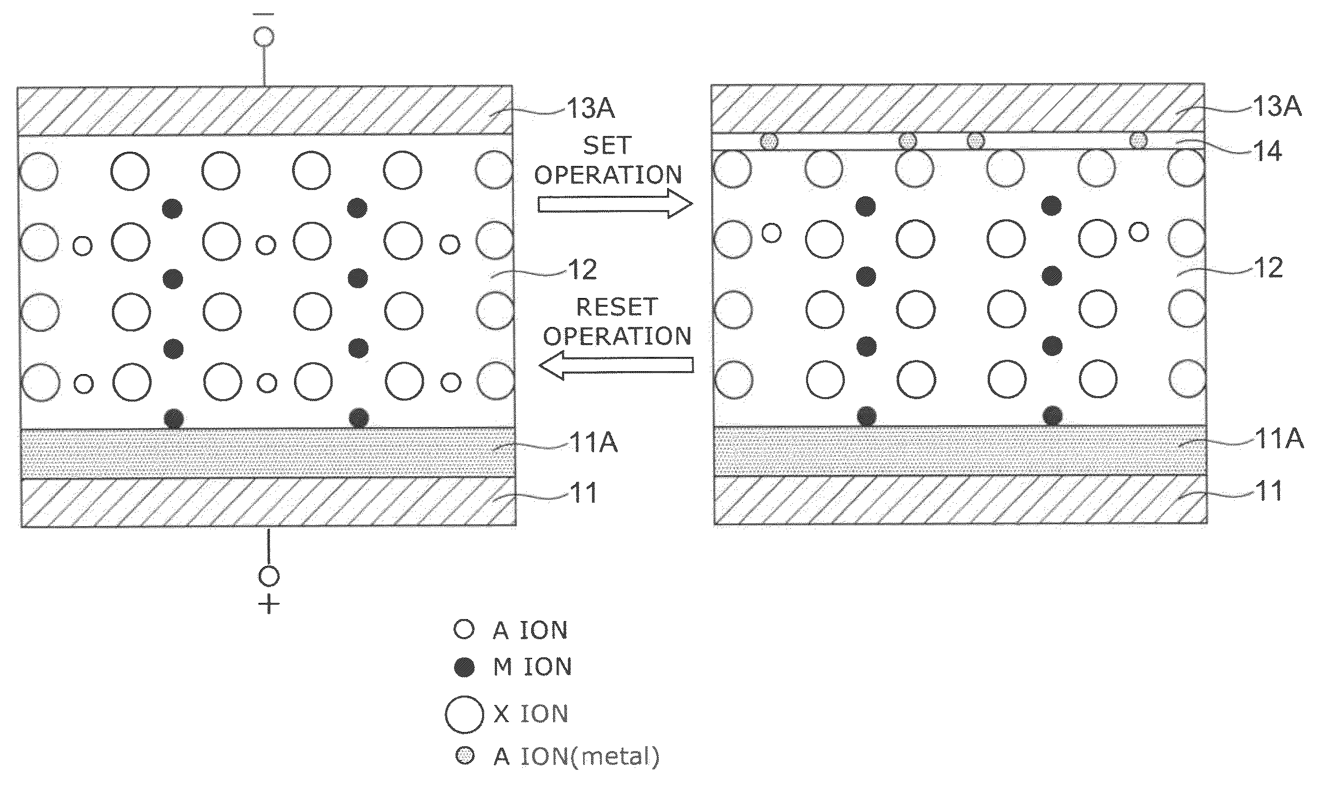
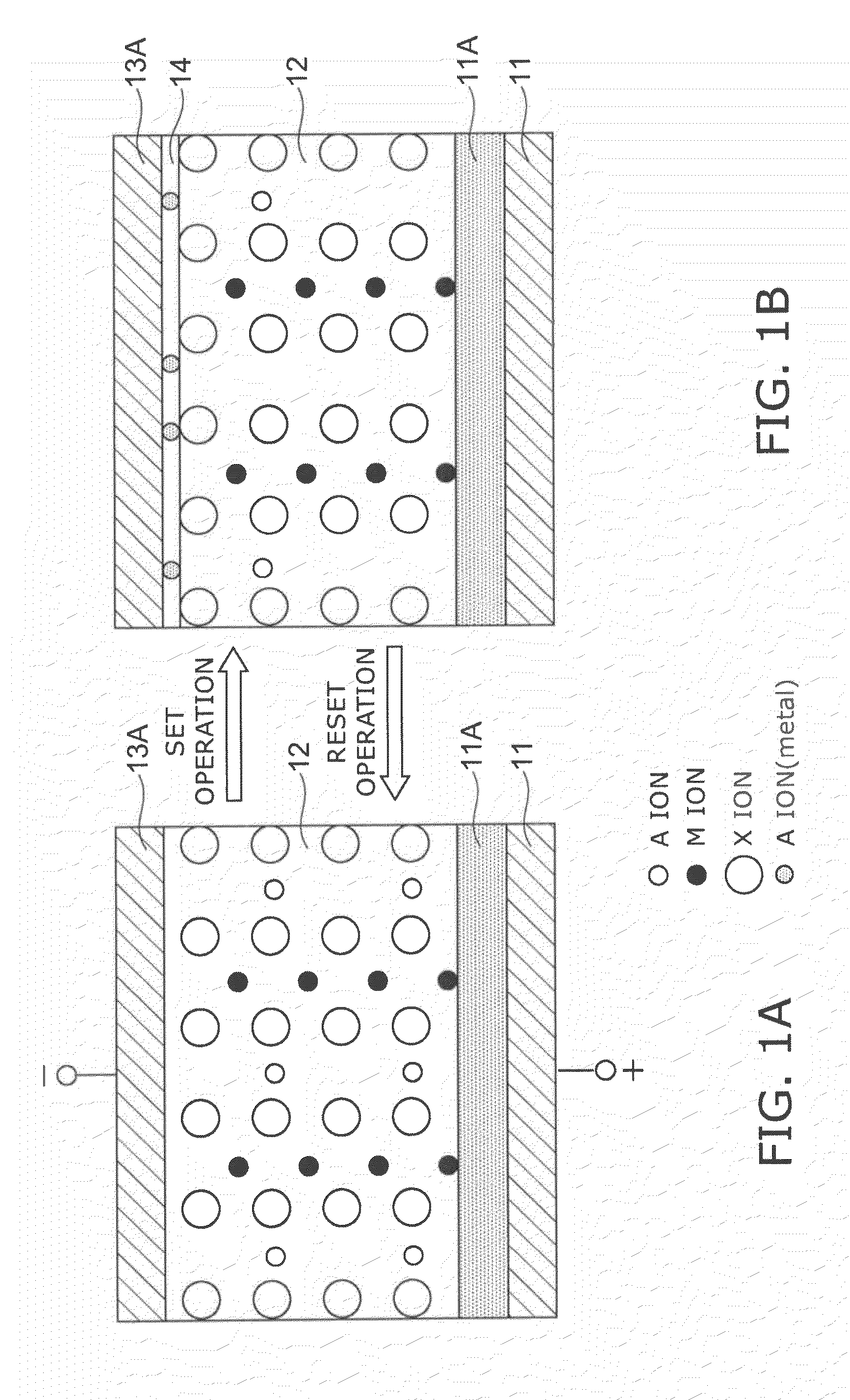
[0100]FIG. 1 is a conceptual view illustrating the basic principle of recording / reproducing information in an information recording and reproducing apparatus according to a first embodiment of the invention.

[0101]FIG. 1A is a cross-sectional view of a recording unit. The recording unit has a structure in which electrode layers 11 and 13A are disposed on either side of a recording layer 12. Further, an orientation control layer 11A is provided between the recording layer 12 and the electrode layer 11.

[0102]The recording layer 12 includes a first compound, where the first compound is a conjugated compound including at least two types of cation elements, at least one selected from the cation elements is a transition element having a d orbit incompletely filled by electrons, and the shortest distance between adjacent cation elements is not more than 0.32 nm. Such a recording layer may include, for example, the following materials.

[0103]One example is a spinel structure represented by Ax...

second embodiment

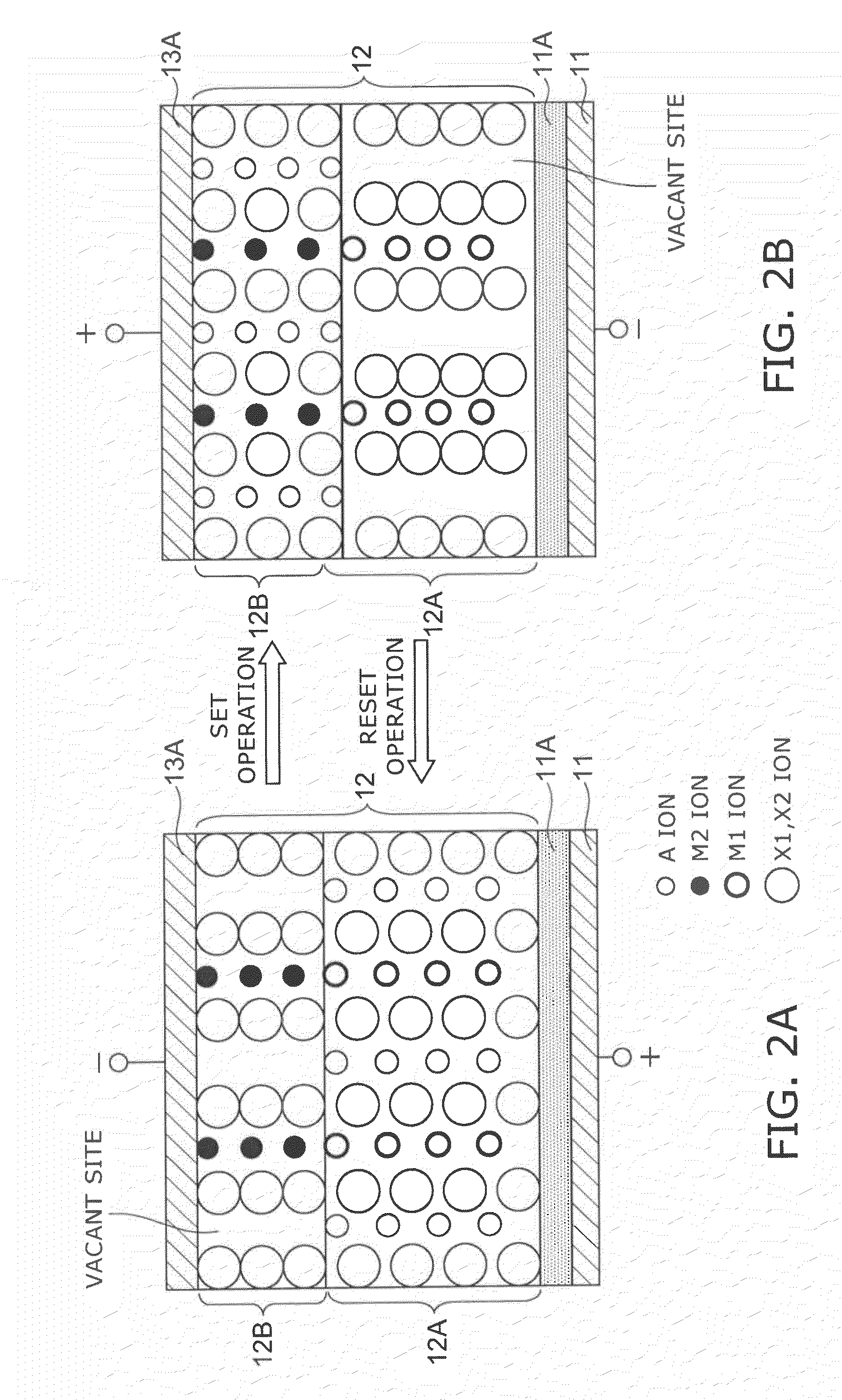
[0248]Next, the basic principle of recording / erasing / reproducing information in an information recording and reproducing apparatus according to a second embodiment of this embodiment will be described.

[0249]FIG. 2 is a conceptual view illustrating the structure of the recording unit of this embodiment.

[0250]The recording unit has a structure in which the electrode layers 11 and 13A are disposed on either side of the recording layer 12. Further, the orientation control layer 11A is provided between the recording layer 12 and the electrode layer 11.

[0251]The recording layer 12 includes a first compound 12A disposed on the electrode layer 11 side and represented by AxM1yX1z and a second compound 12B disposed on the electrode layer 13A side, including at least one type of transition element, and having vacant sites capable of containing the A ion element of the first compound 12A.

[0252]The second compound 12B may include substances such as those represented by, for example, the followin...

first experimental example

[0470]A first experimental example is an example using (100) oriented VN as the orientation control layer and using ZnCr2O4 as the first compound.

[0471]VN was formed in a film on a B-doped Si (100) substrate using a target (with a diameter of 100 mm) having a composition ratio adjusted to deposit VN. The native oxide film of the Si substrate surface is removed beforehand. Although the orientation differs by the power and the pressure during film formation in the case where VN is formed in a film, in the case of this experimental example, RF magnetron sputtering was performed at room temperature in 0.5 Pa argon gas with an RF power of 100 W; and as a result, (100) oriented VN was obtained. The VN film thickness was 50 nm.

[0472]Continuing, ZnCr2O4 was formed in a film as the first compound without removing the substrate from the vacuum chamber. RF magnetron sputtering was performed in an atmosphere of 95% Ar (argon) and 5% O2 (oxygen) using a target having a mixing ratio adjusted such...


PUM


Abstract

An information recording and reproducing apparatus, includes: a recording layer including a first layer including a first compound, the first compound being a conjugated compound including at least two types of cation elements, at least one selected from the cation elements being a transition element having a d orbit incompletely filled by electrons, a shortest distance between adjacent cation elements being not more than 0.32 nm; a voltage application unit that applies a voltage to the recording layer, produces a phase change in the recording layer, and records information; an electrode layer that applies a voltage to the recording layer; and an orientation control layer provided between the recording layer and the electrode layer to control an orientation of the recording layer.

Description

CROSS-REFERENCE TO RELATED APPLICATIONS[0001]This is a continuation application of International Application PCT / JP08 / 060,776, filed Jun. 12, 2008. This application also claims priority to Japanese Application No. 2007-155710, filed on Jun. 12, 2007. The entire contents of each are incorporated herein by reference.TECHNICAL FIELD[0002]The invention relates to an information recording and reproducing apparatus having high recording density.BACKGROUND ART[0003]In recent years, downsized mobile devices have spread worldwide, and simultaneously, the demand for downsized large-capacity nonvolatile memory has rapidly enlarged with the drastic progress of high-speed telecommunications networks. Therein, NAND flash memory and downsized HDDs (hard disk drives) in particular have achieved rapid advancements of recording density to form a large market.[0004]Under such circumstances, several ideas for new memory aiming to drastically exceed the limits of recording density have been proposed. Fo...

Claims


Application Information

Patent Timeline
Patent Type & Authority Patents(United States)
IPC IPC(8): G11C11/00
CPCB82Y10/00G11B9/04G11B9/149G11C13/0004G11C13/0007G11C13/003G11C16/3427H01L27/101H01L27/2409H01L27/2481H01L45/04H01L45/1233H01L45/1253H01L45/126H01L45/147H01L45/1625G11C2213/53G11C2213/75H10B63/84H10B63/20H10N70/20H10N70/8413H10N70/841H10N70/8836H10N70/026H10N70/826
Inventor TSUKAMOTO, TAKAYUKIKUBO, KOHICHIKAMATA, CHIKAYOSHIHIRAI, TAKAHIROAOKI, SHINYAHIRAOKA, TOSHIRO
Owner KK TOSHIBA
Why Eureka
Try Eureka