Container filling plant, such as a beverage bottling plant, for filling containers with a liquid beverage and for closing filled containers

a container and beverage technology, applied in the direction of rotating screw stopper insertion, packaging goods type, packaging, etc., can solve the problems of high production cost, high production cost, and high production cost, so as to minimize the surface area of the machine and the frame exposed, promote cleaning, and minimize the effect of residue accumulation

Active Publication Date: 2011-08-16
KHS GMBH
View PDF13 Cites 10 Cited by
  • Summary
  • Abstract
  • Description
  • Claims
  • Application Information

AI Technical Summary

Benefits of technology

[0028]The object of at least one embodiment is to essentially eliminate the disadvantages of the receiving tables for container handling machines as discussed above, such as, for example, the large amount of material that is required, and the related high manufacturing costs and large surface areas with disadvantageous configurations that tend to collect dirt and contaminants. The present application teaches that the receiving tables of the prior art can be replaced by a simple frame or brace construction with optimized or reduced surfaces.
[0029]The object of at least one other embodiment is to realize a capping machine which has a particularly simple and thus economical construction, and in which the cleaning of the machine is further improved, with a simultaneous reduction of costs. Another object is to design a capping machine that is suitable for use with the novel setup table disclosed herein. This application therefore teaches a capping machine that is connected mechanically and / or for the transmission of force only by a non-rotating central pillar with the space surrounding the capping machine. Additional advantageous developments are discussed herein below.SUMMARY
[0031]The advantages and disadvantages of some types of setup tables are described above. The present application teaches that conventional setup or descrambling tables can be replaced by rod-shaped elements to eliminate said disadvantages.
[0034]In addition, the capping or closing machine as disclosed herein promotes ease of cleaning and minimizes build-up of residues from the bottling process on the machine and support frame. During the bottling process, it is not uncommon for an amount of a liquid in the bottles, after filling, to splash out of the bottles during transport from the filling machine to the capping machine. Further, it is not uncommon for an amount of an effervescent liquid to bubble over and out of the top of the bottles during transport from the filling machine to the capping machine. Consequently, amounts of liquid are often spilled onto the capping machine and support frame during the bottling process, causing the surfaces of the machine and the support frame to become dirty, which could increase the chance for build-up of bacteria that could contaminate the liquid. The design of the capping machine and support frame disclosed herein minimizes the surface area of the machine and frame exposed to spillage, and also increases access to these surfaces by personnel for ease of cleaning of the machine. In addition, the risk of contamination is also thereby decreased.

Problems solved by technology

Because such receiving tables, with all their attendant advantages, represent a significant cost factor on account of the complexity of their design and construction, and the constructions that are disclosed in the prior art had numerous individual surfaces, edges, corners and undercuts that offered starting points for undesirable contamination, multiple attempts have been made in the past to simplify and improve receiving tables with regard to their manufacture, costs and hygiene or cleaning.
One of several disadvantages of a device of this type is that the metal plates used require a large amount of material, and the mechanical processing of this material is complicated, time-consuming and expensive on account of the numerous borings that have to be introduced into these plates at specified angles.
Of course a receiving table of the type described in DE 200 02 483 U1 uses significantly less material compared to other realizations, although the fabrication of the hip-roof superstructure frequently poses technical difficulties.
The realization of the drive system on capping machines of the prior art is also comparatively complicated and expensive.
The components required for this transmission are complicated and expensive to manufacture and assemble.
Capping machines of the prior art located on setup tables or separate frames are also complicated, time-consuming and expensive to clean.
In addition, these types of capping machines are not suitable for use in the novel design of a setup table as described herein below.
Further, it is not uncommon for an amount of an effervescent liquid to bubble over and out of the top of the bottles during transport from the filling machine to the capping machine.
Consequently, amounts of liquid are often spilled onto the capping machine and support frame during the bottling process, causing the surfaces of the machine and the support frame to become dirty, which could increase the chance for build-up of bacteria that could contaminate the liquid.

Method used


Image

  • Container filling plant, such as a beverage bottling plant, for filling containers with a liquid beverage and for closing filled containers
  • Container filling plant, such as a beverage bottling plant, for filling containers with a liquid beverage and for closing filled containers
  • Container filling plant, such as a beverage bottling plant, for filling containers with a liquid beverage and for closing filled containers

Examples


Embodiment Construction

[0044]Developments, advantages and potential applications of the invention are described below with reference to exemplary embodiments and the accompanying drawing. All the features described and / or illustrated, in themselves or in any possible combination, are the object of the invention, regardless of their placement in the claims or the references between claims. The content of the claims is also incorporated by reference into this description.

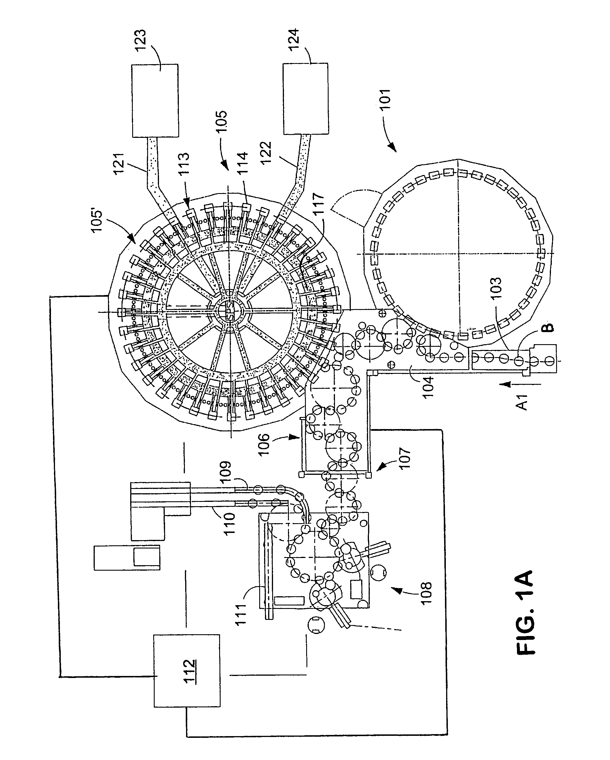
[0045]FIG. 1A shows schematically the main components of one possible embodiment example of a system for filling containers, specifically, a beverage bottling plant for filling bottles B with at least one liquid beverage, in accordance with at least one possible embodiment, in which system or plant could possibly be utilized at least one aspect, or several aspects, of the embodiments disclosed herein.

[0046]FIG. 1A shows a rinsing arrangement or rinsing station 101, to which the containers, namely bottles B, are fed in the direction of trave...


PUM

PropertyMeasurementUnit
rotationaaaaaaaaaa
diameteraaaaaaaaaa
outer diameteraaaaaaaaaa

Abstract

Container filling plant, such as a beverage bottling plant, for filling containers with a liquid beverage and for closing filled containers. The abstract of the disclosure is submitted herewith as required by 37 C.F.R. §1.72(b). As stated in 37 C.F.R. §1.72(b): “A brief abstract of the technical disclosure in the specification must commence on a separate sheet, preferably following the claims, under the heading “Abstract of the Disclosure.” The purpose of the abstract is to enable the Patent and Trademark Office and the public generally to determine quickly from a cursory inspection the nature and gist of the technical disclosure. The abstract shall not be used for interpreting the scope of the claims.” Therefore, any statements made relating to the abstract are not intended to limit the claims in any manner and should not be interpreted as limiting the claims in any manner.

Description

BACKGROUND[0001]1. Technical Field[0002]This application relates to a bottling or container filling plant for filling containers, such as bottles, with a liquid beverage, and for closing filled containers. This application also relates to a beverage bottling plant for filling bottles with a liquid beverage filling material having a receiving table or unscrambling table or setup table or prep table for the container handling machines therein.[0003]This application further relates to a device and / or a closing or capping machine employing a rotary construction for the capping of containers such as, for example, bottles or similar containers with screw tops or crown corks with a rotating carousel on which a plurality of container capping positions, each equipped with a capping element, are formed. Advantageous developments and other embodiments are described herein below.[0004]2. Background Information[0005]A beverage bottling plant for filling bottles with a liquid beverage filling mat...

Claims


Application Information

Patent Timeline
Patent Type & Authority Patents(United States)
IPC IPC(8): B67B6/00B67B1/06
CPCB67B3/2033B67C3/02B67C3/026B67C3/242B67C7/004
Inventor BERNHARD, HERBERT
Owner KHS GMBH
Why Eureka
Try Eureka