

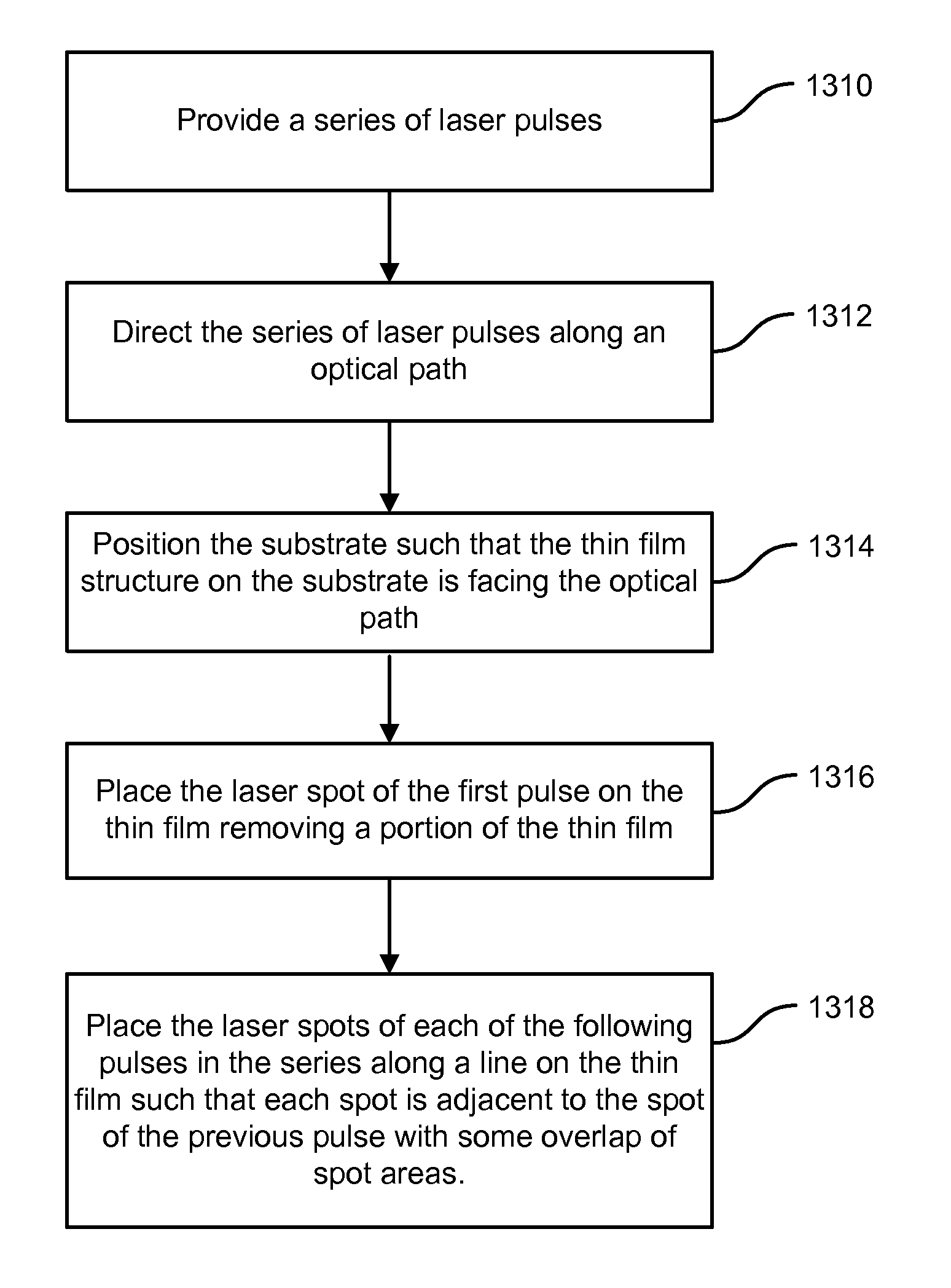
Method and apparatus for scribing a line in a thin film using a series of laser pulses
a laser pulse and thin film technology, applied in metal working equipment, manufacturing tools, welding/soldering/cutting articles, etc., can solve the problems of incomplete removal of thin film material, rough edges, and quality of process, so as to improve the quality and yield of thin film scribing process, and improve the effect of quality and yield
- Summary
- Abstract
- Description
- Claims
- Application Information
AI Technical Summary
Benefits of technology
Problems solved by technology
Method used
Image

Examples
Embodiment Construction
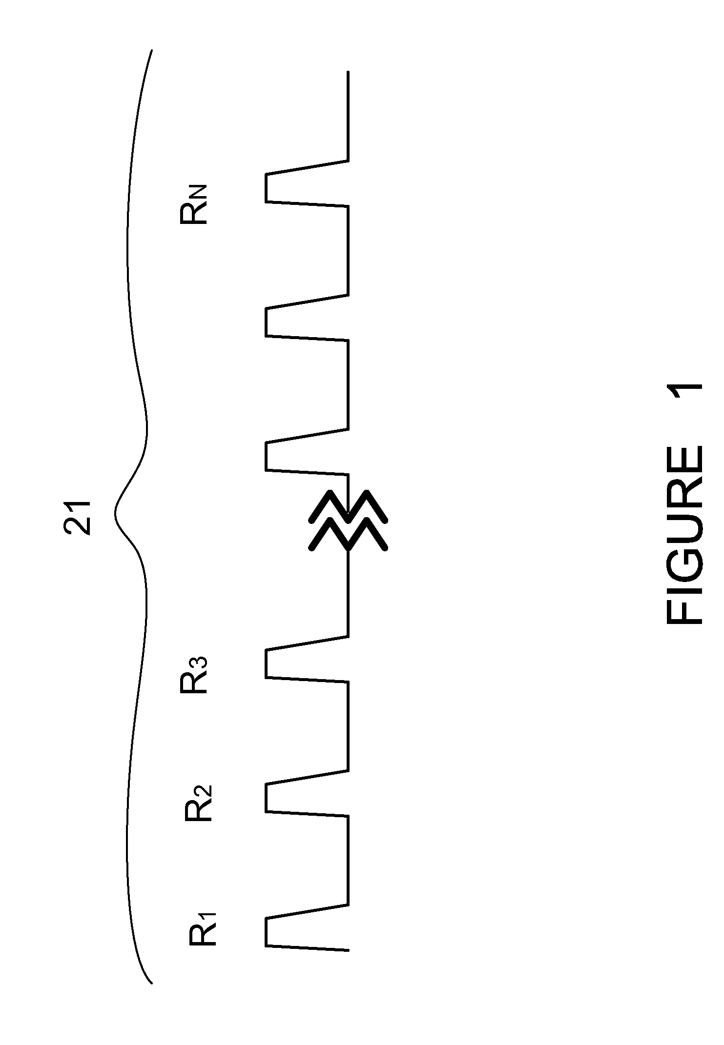
[0038]In the manufacturing process of devices such as solar cells, flat panel displays, and digital displays, a design often includes a thin film of materials deposited on a substrate part of which film must be segmented by scribing a grooved line or pattern in the material, thereby segmenting or patterning the material. This pattern may be a simple line or a more complex pattern of rectangles or other shapes as required in the design of the device. Scribing a line using a pulsed laser is a multiple pulse process using a series of many laser pulses whereby each pulse is focused or imaged to a spot on the thin film and the spot is scanned along the desired line to be scribed such that there is some overlap between each spot with the previous spot and the following spot. The width of the scribed line is determined primarily by the size of the focused laser spot. Widths of lines laser scribed in such thin films typically range from 10 μm to 100 μm although narrower or wider lines can b...
PUM
| Property | Measurement | Unit |
|---|---|---|
| thickness | aaaaa | aaaaa |
| thickness | aaaaa | aaaaa |
| thickness | aaaaa | aaaaa |
Abstract
Description
Claims
Application Information