

Coil device
a coil device and coil technology, applied in the direction of transformer/inductance details, printed inductance, inductance, etc., can solve the problems of over-planar inductor device, unsolved, power transmission efficiency, waste of energy, etc., to achieve good high frequency characteristics, reduce waste of energy, and reduce waste of energy.
- Summary
- Abstract
- Description
- Claims
- Application Information
AI Technical Summary
Benefits of technology
Problems solved by technology
Method used
Image

Examples
Embodiment Construction
[0023]Preferred embodiments of a sheet-like or thin plate-like coil device of the present invention will be hereinafter described in detail referring to the attaching drawings
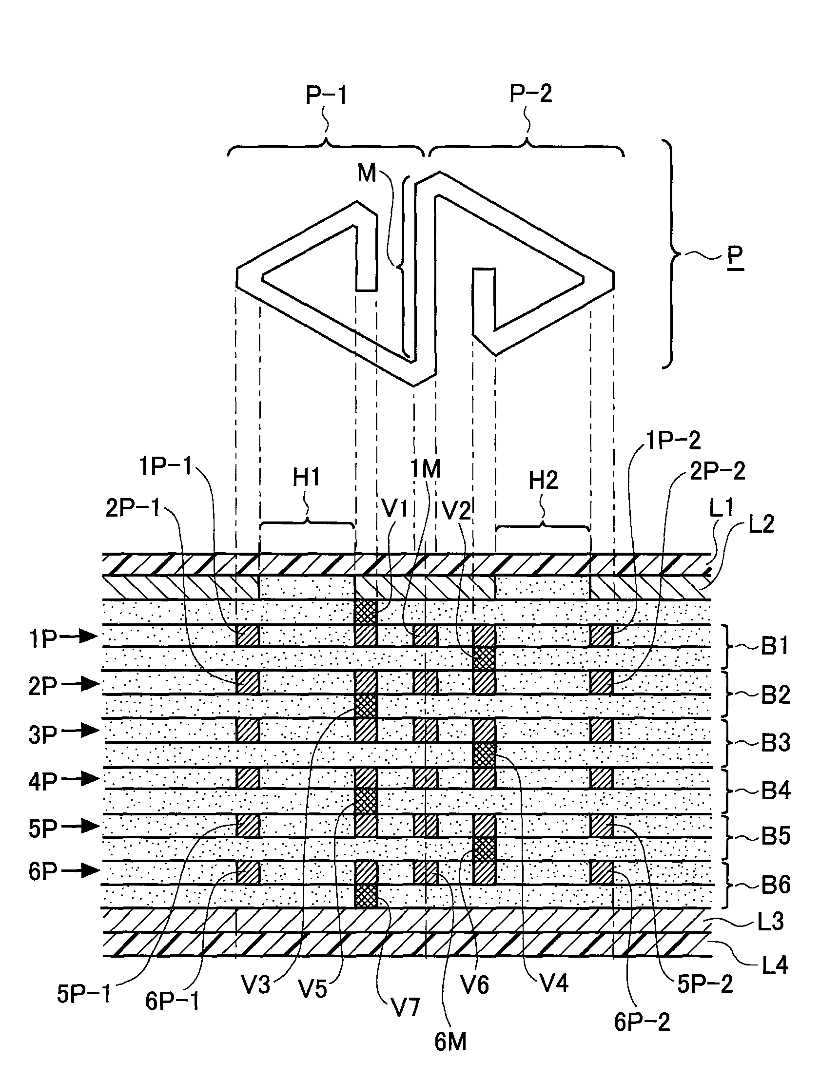
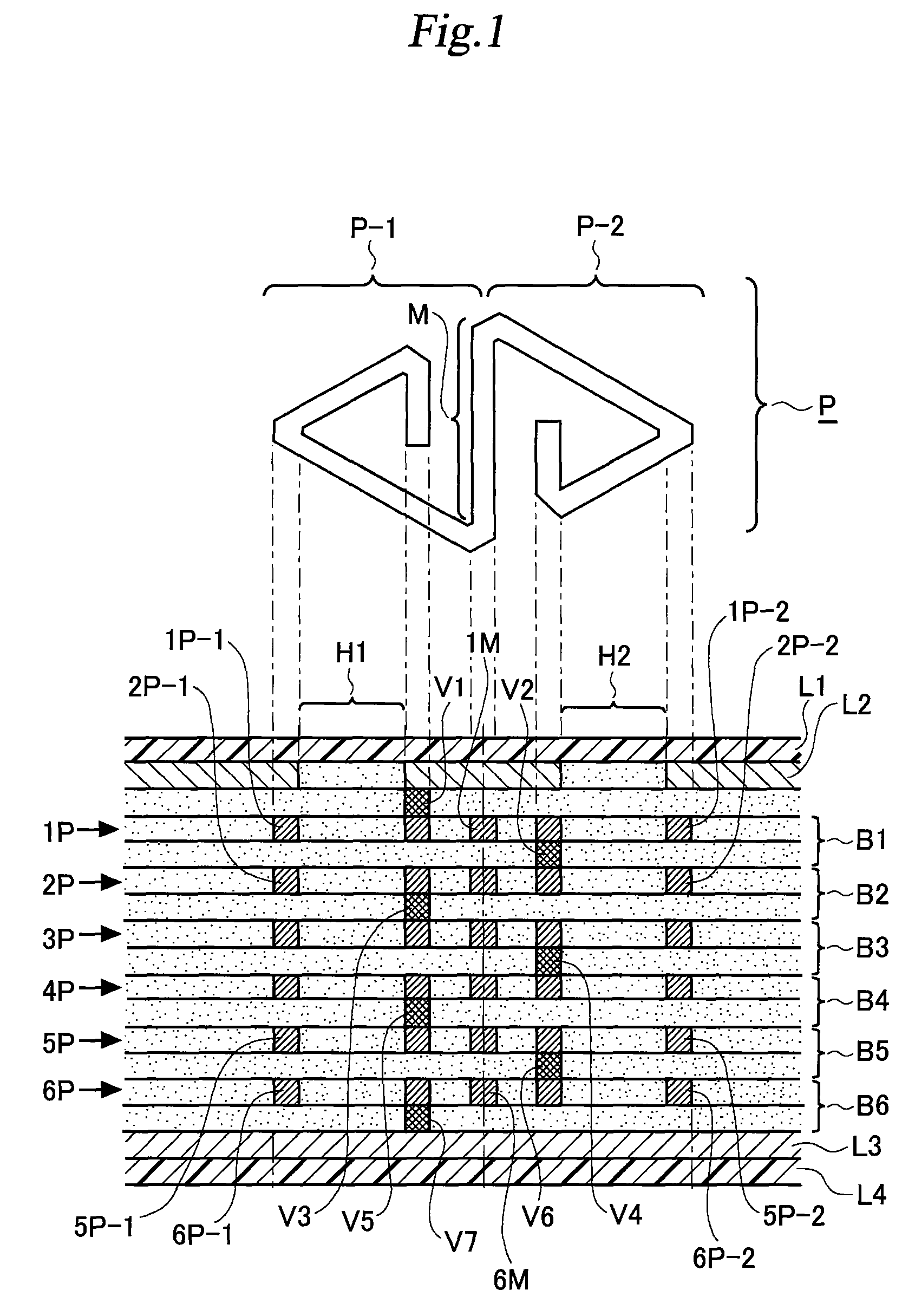
[0024]A sectional view illustrating a structure of a coil device (air core) according to the present invention is shown in FIG. 1. This coil device may be produced using a manufacturing technique applied to multilayer print connection boards (PCB).
[0025]As is apparent in the Figure, this coil device is configured by stacking six print connecting boards (flat coil carry layers) consisting of first board B1 to sixth board B6. L1 denotes upper side insulation coating, L2 denotes upper side power source layer (first interconnection layer), L3 denotes lower side power source layer (second interconnection layer), and L4 denotes lower side insulation layer.
[0026]Upper side power source layer L2 is configured as a conductive surface (solid conductor) having conductivity with uniformity in the whole surface except magne...
PUM
| Property | Measurement | Unit |
|---|---|---|
| inner angles | aaaaa | aaaaa |
| internal angles | aaaaa | aaaaa |
| inner angle | aaaaa | aaaaa |
Abstract
Description
Claims
Application Information