
Methods of manufacturing composite slickline cables

a technology of composite slickline cables and wirelines, which is applied in the field of manufacturing wireline composite slickline cables, can solve the problems of difficulty in removing the oil or gas trapped in the cable, inherently low strength, and the inability to use the slickline cable with much pull force, and achieves uniform circular cross-sectional shape and minimize the variation in diameter

Active Publication Date: 2011-08-16
SCHLUMBERGER TECH CORP
View PDF18 Cites 15 Cited by
  • Summary
  • Abstract
  • Description
  • Claims
  • Application Information

AI Technical Summary

Benefits of technology

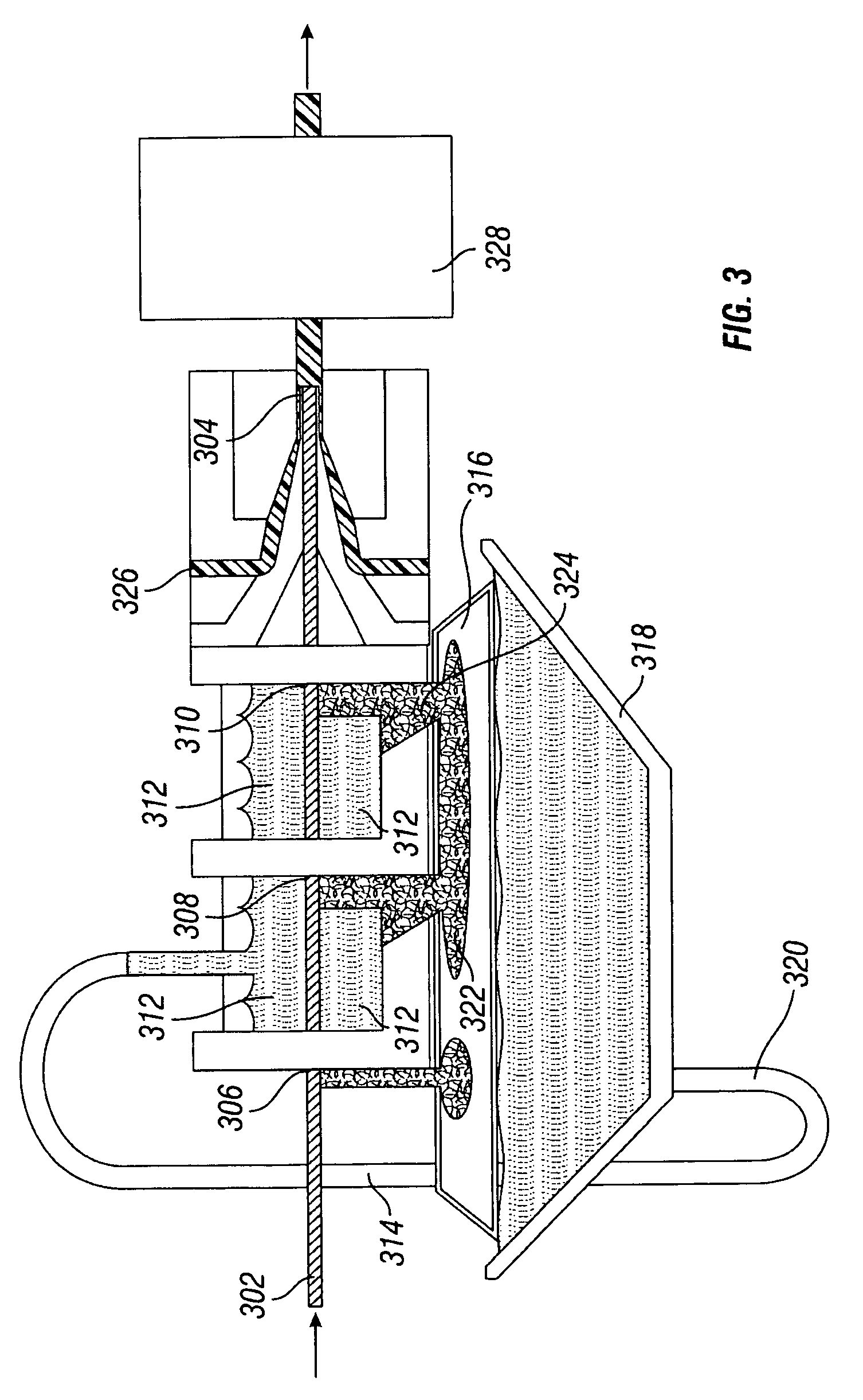
This patent is about a method of manufacturing wellbore slickline electric cables and the use of such cables in measuring the properties of subterranean formations. The method involves preparing a slickline cable by disposing an inner metallic tube containing at least one conductor and an epoxy / fiber composite strength layer substantially upon the outer periphery of the inner metallic tube. An outer metallic tube is then drawn around the combination of the composite strength member and the inner metallic tube to form a wellbore slickline. The invention also includes the use of techniques for minimizing the variation in diameter and providing a substantially uniform circular cross-sectional shape of the combination of the composite strength member and the inner metallic tube. The technical effects of this patent include improved manufacturing methods for wellbore slickline cables and improved methods of measuring the properties of subterranean formations.

Problems solved by technology

Formations generally comprising shale, which may also encapsulate oil-bearing formations, may have porosities much greater than that of sandstone or limestone, but, because the grain size of shale is very small, it may be very difficult to remove the oil or gas trapped therein.
The tubes are typically made of Iconel® which is non-corrosive, but is inherently low in strength.
This lack of strength prevents these slickline cables from being used with much pull force.
Because slickline cables have metallic tubes and are used with relatively small sheaves (16 to 20 in. in diameter) they are also prone to yielding and failure as they pass over sheaves.
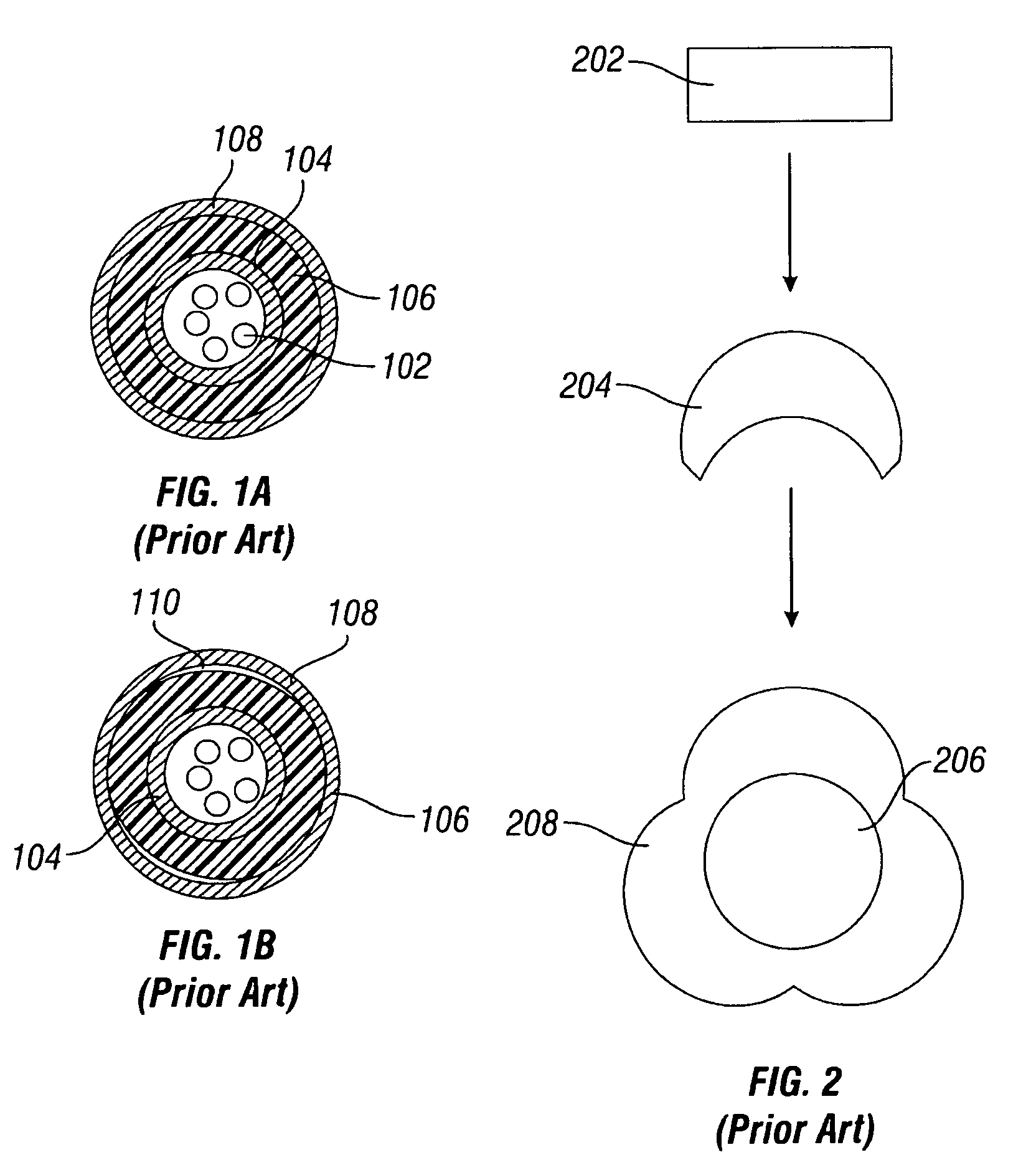
Also, in some instances, loose fibers on the surface of the epoxy / fiber composite material 106 can build up at the entrances to extrusion tip and lead to jamming / interruption of the manufacturing process line.
This causes several problems.
First, because the profile can be as much as 7 to 15 mil out of round, an equivalent amount of coating would be required, thereby increasing the line's diameter, and most often, there is no space available in slickline cables to allow for coatings of that thickness.
Second, applying compression-extruded polymer over the epoxy / long fiber composite reheats the epoxy.
This reheating releases moisture and other volatile residues causing blistering of the extruded polymer.
Third, loose fibers or fuzz from the epoxy / fiber composite collect at the back of the tip of the extruder head due to fuzz build-up from the cured pultruded core.
This leads to jamming at the tip of the extruder and cable breaks, which prevents long-length extrusions.
Such a cloverleaf shade not only has significant variation in diameter about the periphery, but also varied domains of relative fiber / epoxy concentrations which may result in further weakening and making the cable less durable.

Method used


Image

  • Methods of manufacturing composite slickline cables
  • Methods of manufacturing composite slickline cables
  • Methods of manufacturing composite slickline cables

Examples


Embodiment Construction

[0025]The description and examples are presented solely for the purpose of illustrating the preferred embodiments of the invention and should not be construed as a limitation to the scope and applicability of the invention. While the some embodiments of the invention are described herein as comprising certain materials, it should be understood that the composition could optionally comprise two or more different materials. In addition, the composition can also comprise some components other than the ones already cited. In the summary of the invention and this detailed description, each numerical value should be read once as modified by the term “about” (unless already expressly so modified), and then read again as not so modified unless otherwise indicated in context.

[0026]The invention relates to wellbore slickline electric cables, and methods of manufacturing and using such cables, and particularly methods of manufacturing composite slickline cables. The methods of the invention pr...


PUM

PropertyMeasurementUnit
diameteraaaaaaaaaa
diameteraaaaaaaaaa
diameteraaaaaaaaaa

Abstract

Disclosed are wellbore electric cables, and methods of manufacturing such cables, and in one aspect, methods of manufacturing wireline composite slickline cables. Some embodiments are methods which include preparing a slickline cable by providing an inner metallic tube containing at least one conductor (such as an optical fiber), disposing an epoxy / fiber composite strength layer substantially upon the outer periphery of the inner metallic tube, and exposing the combination of the inner metallic tube and composite strength layer to at least one technique for minimizing the variation in diameter and providing a substantially uniform circular cross-sectional shape of the combination. Further, an outer metallic tube is draw around the combination of the composite strength member and the inner metallic tube, to form a wellbore slickline. Cables prepared using such methods are also disclosed.

Description

[0001]This non-provisional patent application claims priority to provisional application Ser. No. 60 / 681,421 filed May 16, 2005.BACKGROUND OF THE INVENTION[0002]This invention relates to wellbore slickline electric cables, and methods of manufacturing and using such cables. In one aspect, the invention relates to a method of manufacturing wireline composite slickline cables.[0003]Generally, geologic formations within the earth that contain oil and / or petroleum gas have properties that may be linked with the ability of the formations to contain such products. For example, formations that contain oil or petroleum gas have higher electrical resistivity than those that contain water. Formations generally comprising sandstone or limestone may contain oil or petroleum gas. Formations generally comprising shale, which may also encapsulate oil-bearing formations, may have porosities much greater than that of sandstone or limestone, but, because the grain size of shale is very small, it may ...

Claims


Application Information

Patent Timeline
Patent Type & Authority Patents(United States)
IPC IPC(8): G02B6/44B29C48/06
CPCB29C47/0004B29C47/0016B29C47/0023B29C47/003B29C47/28B29C47/903B29C70/086B29C70/088B29C70/521B29C53/58B29K2063/00B29K2301/10B29L2031/707B29C48/022B29C48/06B29C48/09B29C48/10B29C48/12B29C48/13B29C48/34B29C48/903B29C48/908
Inventor VARKEY, JOSEPH
Owner SCHLUMBERGER TECH CORP
Learn More