Pseudo common-path DPSK demodulator

a technology of demodulator and common path, applied in the field of differential phaseshift keying (dpsk) in telecommunication, can solve the problem of reducing the sensitivity of the device to environmental changes, and achieve the effect of simplifying the manufacturing process and reducing the sensitivity of the devi

Active Publication Date: 2011-08-23
OPTOPLEX CORP
View PDF11 Cites 11 Cited by
  • Summary
  • Abstract
  • Description
  • Claims
  • Application Information

AI Technical Summary

Benefits of technology

[0011]This invention is based on the idea of using a rhomb beam splitter, rather than a conventional cube, in combination with a mirror reflecting both the reflected and transmitted beams. Using a rhomb beam splitter, so long as the beam splitting surface and the reflective surface of the rhomb structure are parallel and the exit surface is flat, the reflection and transmission beams from the beam splitter will remain parallel to each other toward the reflector regardless of the alignment of the beam splitter with the input beam. Therefore, a single reflector may be used to reflect both beams. These two beams travel together so closely that they are almost in a common path. This significantly reduces the sensitivity of the device to environmental changes and also greatly simplifies the manufacturing process.
[0013]In another embodiment of the invention, four additional components are used to perfect the performance of the device. A wave plate is used in the path of the reflected beam to compensate for the polarization differential phase introduced by the coating on the beam splitter and on the top reflective surface of the rhomb structure. A thermal phase tuner with a micro-heater is also added in the reflected beam's path to tune the phase of the pseudo common path by varying the temperature of the phase tuner. A first compensator is used in the path of the transmitted beam to cancel the spectral thermal drift introduced by the difference in the lengths of the paths traveled by the reflected and transmitted beams in the glass structure of the rhomb splitter. Finally, a second compensator made of the same material and thickness as the phase tuner is used in the path of the transmitted beam to compensate for the thermal drift of the phase tuner introduced by environmental causes.

Problems solved by technology

This significantly reduces the sensitivity of the device to environmental changes and also greatly simplifies the manufacturing process.

Method used


Image

  • Pseudo common-path DPSK demodulator
  • Pseudo common-path DPSK demodulator
  • Pseudo common-path DPSK demodulator

Examples


Embodiment Construction

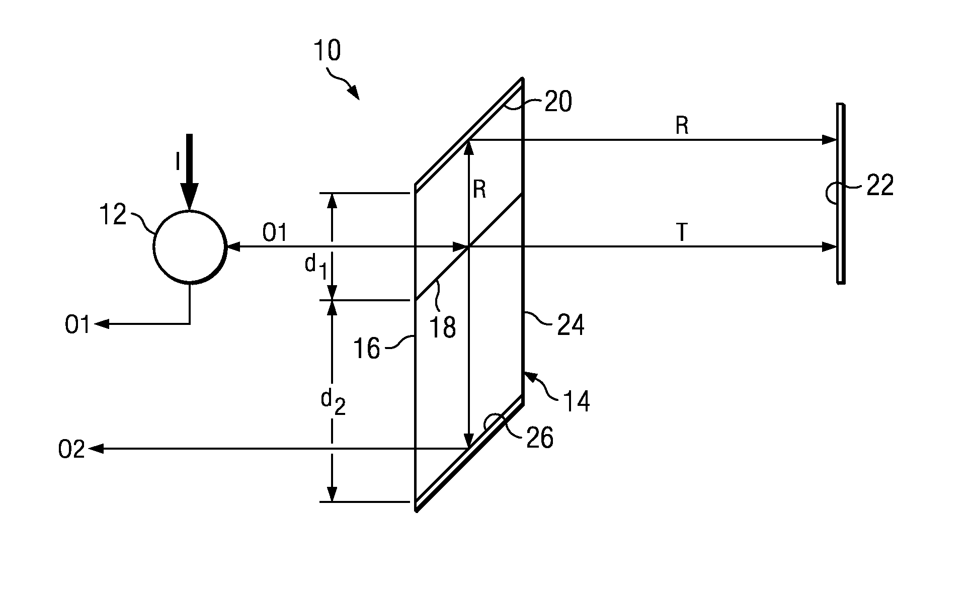
[0026]For the purposes of this disclosure, the term “rhomb” is used throughout for simplicity, but it is understood that the precise geometric definition of the beam-splitter structure illustrated in the figures is that of a parallelepiped (that is, a three-dimensional figure formed by six parallelograms, a parallelogram being a quadrilateral with two sets of parallel). However, as mentioned, the only critical feature of the beam-splitter structure of the invention is that it must include a beam-splitting surface and a mirror surface that are parallel. Therefore, the invention is not to be limited to any particular form of beam-splitter structure even though the term rhomb, for a common structure used in the art, has been used throughout for convenience to describe generally all forms that are suitable for practicing the invention.

[0027]Referring to the figures, wherein like reference numerals and symbols are used throughout to refer to the same components, FIG. 1 illustrates schema...


PUM

PropertyMeasurementUnit
optical path differenceaaaaaaaaaa
optical lengthaaaaaaaaaa
phaseaaaaaaaaaa

Abstract

A rhomb beam splitter, rather than a conventional cube, is used in combination with a mirror reflecting both the reflected and transmitted beams to obtain a delay-line interferometer demodulator with a substantially common path. This significantly reduces the sensitivity of the device to environmental changes and also greatly simplifies the manufacture process. A polarization-insensitive coating or a wave plate, a thermal phase tuner with a micro-heater, and two compensator plates are used in the paths of the beams to balance the optical path lengths and to compensate for polarization and environmental effects.

Description

RELATED APPLICATIONS[0001]This application is based on and claims the priority of U.S. Provisional Application Ser. No. 61 / 135,356, filed Jul. 19, 2008 and U.S. Provisional Application Ser. No. 61 / 084,229, filed Jul. 28, 2008.BACKGROUND OF THE INVENTION[0002]1. Field of the Invention[0003]This invention relates to differential phase-shift keying (DPSK) in telecommunication. More specifically, it relates to methods in DPSK for converting a phase-keyed signal to an intensity-keyed signal.[0004]2. Description of the Prior Art[0005]Phase-shift keying (PSK) is a digital modulation scheme that conveys data by changing, or modulating, the phase of a reference signal (the carrier wave). Any digital modulation scheme uses a finite number of distinct signals to represent digital data. In the case of PSK, a finite number of phases is used. Each of these phases is assigned a unique pattern of binary bits. Usually, each phase encodes an equal number of bits. Each pattern of bits forms the symbol...

Claims


Application Information

Patent Timeline
Patent Type & Authority Patents(United States)
IPC IPC(8): G02F2/00G02B1/10
CPCH04B10/677G02F2/00
Inventor HSIEH, YUNG-CHIEHAL, CHIAYU
Owner OPTOPLEX CORP
Why Eureka
Try Eureka