Method and apparatus of water cooling several parallel circuit cards each containing several chip packages

a technology of parallel circuit cards and water cooling, which is applied in the direction of electrical apparatus casings/cabinets/drawers, power cables, semiconductor/solid-state device details, etc., can solve the problems of insufficient air cooling, difficult cooling of circuits, and insufficient cooling of additional cooling needs for more powerful heat producing electronic devices

Inactive Publication Date: 2011-08-23
GLOBALFOUNDRIES INC
View PDF65 Cites 61 Cited by
  • Summary
  • Abstract
  • Description
  • Claims
  • Application Information

AI Technical Summary

Problems solved by technology

However, in the electronics industry, more powerful circuits are difficult to cool using air cooling and even for relatively low-power devices air cooling can be inadequate.
Although such enhancements to air cooling remove additionally heat, they have proved to be inadequate for providing the additional cooling need for more powerful heat producing electronic devices.
It is particularly difficult to cool these devices in any other manner, for example water cooling, because the heat produced by the DRAMs is spread evenly over the several DRAMs and there is limited space between them.
Water cooling lends itself to a concentrated heat source, thus current cooling systems are unable to take advantage of water cooling.
Another shortcoming with prior art devices is the inability to conveniently remove and replace a device that is liquid cooled.
The level of control needed is usually beyond what can be done in the field, so an individual liquid cooled device cannot easily be replaced in the field.
Connections such as these take up a considerable volume of space.
While practical for one or a few devices, having an individual liquid disconnect for many devices uses too much room, making this solution impractical.

Method used


Image

  • Method and apparatus of water cooling several parallel circuit cards each containing several chip packages
  • Method and apparatus of water cooling several parallel circuit cards each containing several chip packages
  • Method and apparatus of water cooling several parallel circuit cards each containing several chip packages

Examples


Embodiment Construction

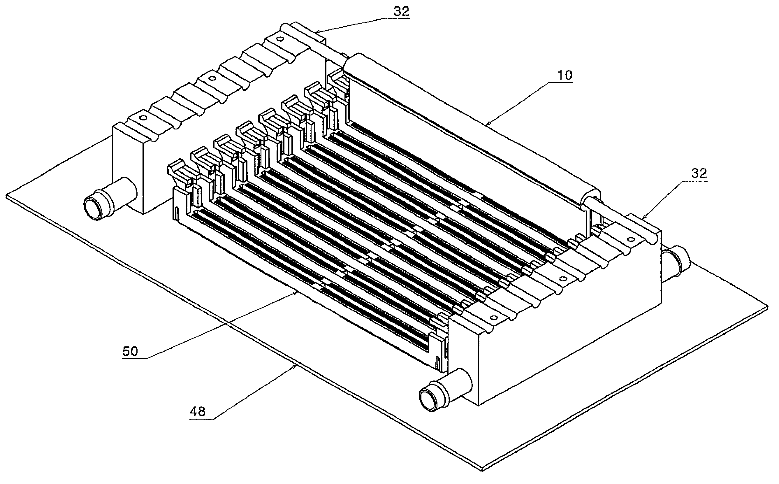
[0037]Illustrative embodiments of the present invention are described herein with reference to FIGS. 1-23 for apparatuses and methods of cooling heat producing electronic devices. For example, the apparatuses provide cooling for several parallel circuit cards including chip packages while allowing the circuit cards to be replaced in the field and further without disturbing any fluid or liquid (e.g., water) connections.

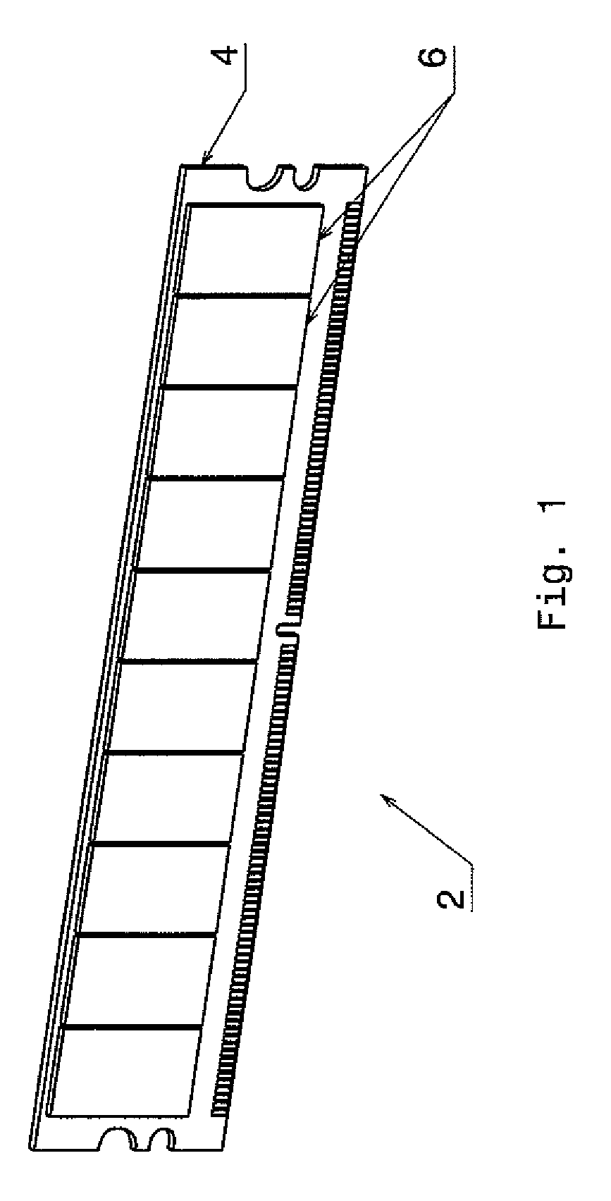
[0038]Referring to FIG. 1, an illustrative embodiment of a heat producing electronic device is a typical dual in-line memory module (DIMM) 2 that is used in computers. The DIMM includes a circuit card 4 and several dynamic random access memory chips (DRAMs) 6. Several of these DIMMs 2 are typically plugged into a computer processor printed circuit board in a parallel manner and in close proximity to each other, typically about 12 mm apart.

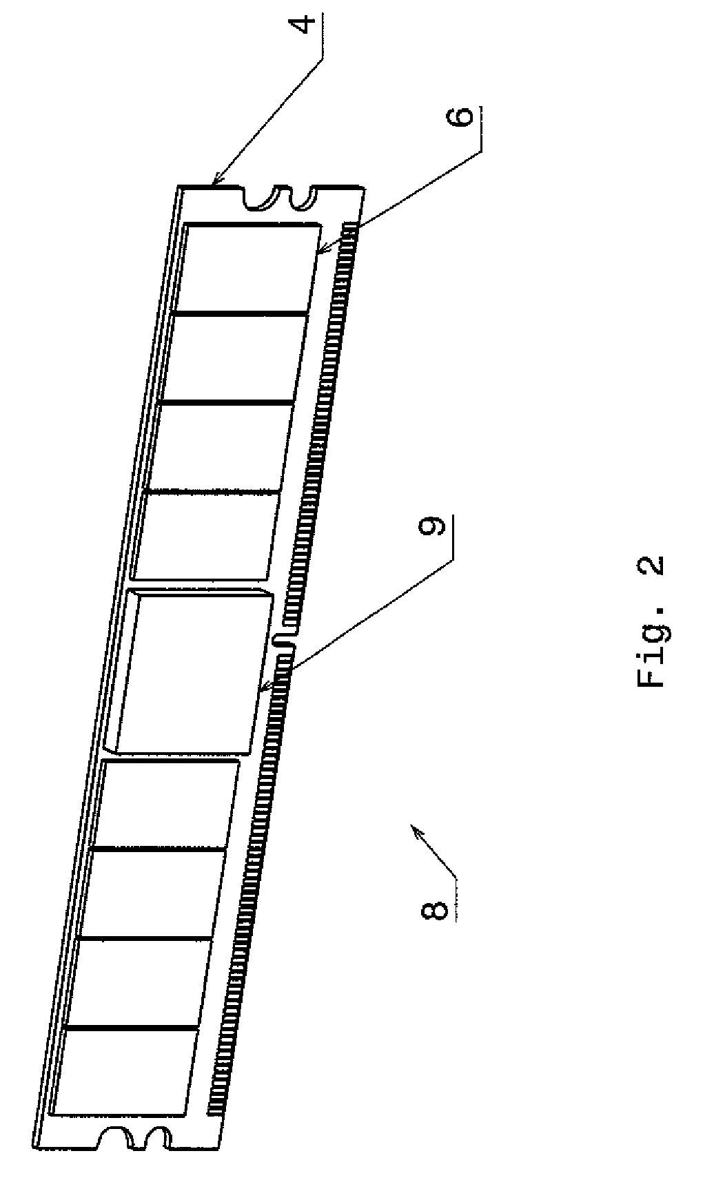
[0039]Another embodiment of a DIMM 8 is shown in FIG. 2, wherein in addition to the DRAMs 6, a memory controller chip package 9 is a...


PUM


Abstract

A cooling or heat transfer apparatus and method is disclosed for cooling an electronic device. The apparatus includes a heat producing electronic device which may include an electronic circuit card with many heat sources. A heat transfer device is connected to the heat producing electronic device which is thermally communicating with the heat producing device for transferring heat from the heat producing device to the heat transfer device. A heat conduit is connected to the heat transfer device and thermally communicating with the heat transfer device for transferring heat to the heat conduit from the heat transfer device. A cooling housing is connected to the heat conduit and the cooling housing thermally communicating with the heat conduit for transferring heat to the cooling housing from the heat conduit. The apparatus enables the replacement of circuit cards in the field because it eliminates the need to apply thermal-interface materials.

Description

[0001]This invention was made with Government support under Contract No. HR0011-07-9-0002 awarded by Defense Advanced Research Projects Agency (DARPA). The Government has certain rights in this invention.FIELD OF THE INVENTION[0002]The present invention is related to apparatuses and methods for cooling an electronic device, and more specifically, cooling a heat producing electronic device using heat transfer devices.BACKGROUND OF THE INVENTION[0003]Cooling for electronic devices, for example, closely spaced electronic circuit cards with nearly uniform height components, such as dual in-line memory modules (DIMMs), has traditionally been accomplished by circulating air. However, in the electronics industry, more powerful circuits are difficult to cool using air cooling and even for relatively low-power devices air cooling can be inadequate. Alternative cooling methods include using a one piece flat sheet metal heat sink. Although such enhancements to air cooling remove additionally h...

Claims


Application Information

Patent Timeline
Patent Type & Authority Patents(United States)
IPC IPC(8): H05K5/00H05K7/20F28F7/00G06F1/20F28D15/00
CPCF28D15/0233F28D15/0275H01L23/473F28F2275/085H01L2924/0002H01L2924/00
Inventor CIPOLLA, THOMAS M.TIAN, SHURONGCOLGAN, EVAN GEORGECOTEUS, PAUL W.HALL, SHAWN ANTHONY
Owner GLOBALFOUNDRIES INC
Why Eureka
Try Eureka