Water cooling system of engine and cooling method thereof

A technology of a water cooling system and a cooling method, which is applied in the cooling of the engine, engine components, machines/engines, etc., can solve the problems of poor engine, low control accuracy, and lowering the crankshaft starting speed of the engine driven engine, and achieves the starting success rate and Beneficial start-up time, reduced exhaust pollution, improved economy effects

Inactive Publication Date: 2006-12-27
BYD CO LTD
View PDF0 Cites 50 Cited by
  • Summary
  • Abstract
  • Description
  • Claims
  • Application Information

AI Technical Summary

Problems solved by technology

[0003] 1. When the engine starts, especially when it is cold, the water pump and the cooling fan run simultaneously under the drive of the engine. First, the power of the engine is lost, because the temperature of the engine is still low at this time, and rapid heat dissipation is not needed. When the water pump and fan are used, the engine crankshaft's starting speed will be reduced, which will have a certain impact on the engine's starting success rate and starting time. , the temperature rise of the engine coolant will be relatively slow, resulting in low cylinder temperature, poor fuel atomization and evaporation, leading to a large proportion of incomplete fuel combustion, and a large amount of gas such as HC (hydrocarbons) and CO ( carbon monoxide) air pollutants, causing harmful gas emissions
[0004] 2. Since the cycle time of the engine coolant is controlled by the thermostat, this will have a certain impact on the performance of the engine because of the low control accuracy, that is, the control of the cycle time of the engine coolant is lacking. influences
Therefore, when the engine speed changes, the flow rate of the coolant and the cooling capacity of the fan will change accordingly, which may cause a sharp rise in the temperature of the coolant due to the large amount of heat generated by the engine that cannot be dissipated quickly in time, resulting in a sharp increase in the temperature of the coolant. The engine is in bad condition

Method used


Image

  • Water cooling system of engine and cooling method thereof
  • Water cooling system of engine and cooling method thereof
  • Water cooling system of engine and cooling method thereof

Examples


Embodiment Construction

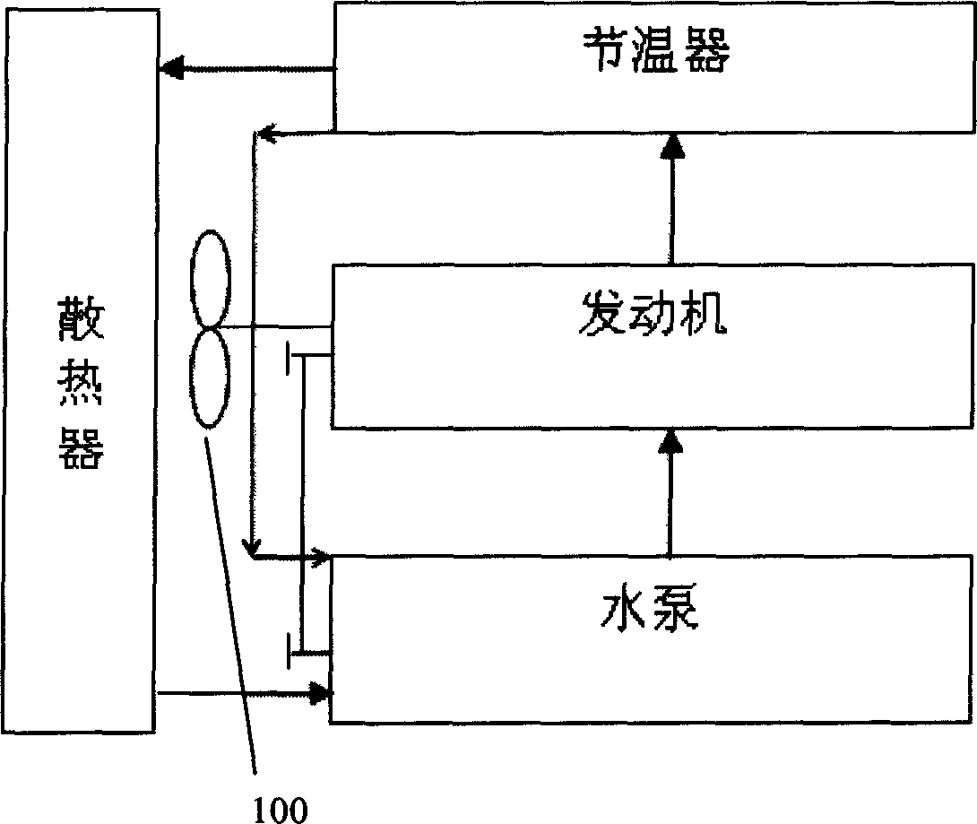
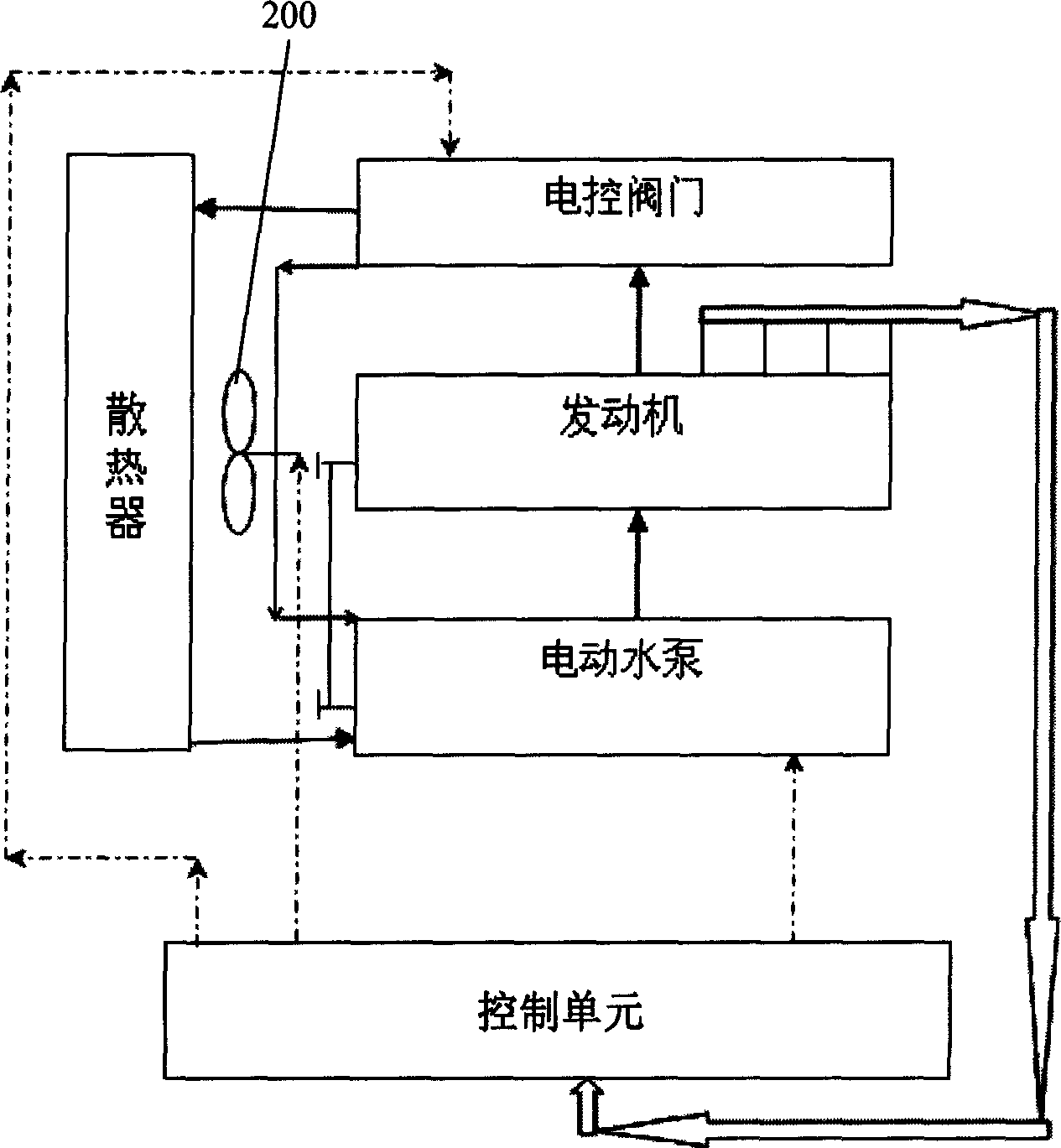
[0040] Such as figure 2 As shown, the water cooling system includes an engine, a first sensor, a coolant temperature sensor, an electric water pump, a circulating water channel, and an electronic control unit. The first sensor is used to sense the operating conditions of the engine, which can be an engine speed sensor, and can also include an engine section. Valve position sensor and engine load sensor. The coolant temperature sensor is used to sense the temperature of the coolant in the engine. It can further include electronically controlled valves, a radiator and an electric fan 200 . The control unit responds to the signals of the engine speed sensor, engine throttle position sensor, engine load sensor and coolant temperature sensor, and controls the electric water pump, electric control valve and electric fan respectively after processing. The circulating water channel can include small circulation and large circulation. The coolant in the small circulation can be driv...


PUM


Abstract

The invention relates to an engine water cooling system and relative cooling method, wherein the first sensor senses the working condition of engine; the cooling liquid temperature sensor senses the temperature of cooling liquid inside the engine; the control unit responds the signals of first sensor and the cooling liquid temperature sensor, to control the electric water pump to operate when the temperature of cooling liquid is higher than the first preset temperature when the engine starts, to drive the cooling liquid to cool the engine, to improve the starting property of engine and the discharging property of heating machine; and the electric controller based on the operation parameter of engine and the temperature of cooling liquid, controls the switch of electric valve, the electric water pump and the rotation speed of electric fan, to control the circulation and the flux of cooling liquid, and the cooling ability of cooling fan, to improve the property of engine.

Description

【Technical field】 [0001] The invention relates to an engine water cooling system and a cooling method. 【Background technique】 [0002] At present, the most commonly used cooling system for automobiles at home and abroad is the engine water cooling system. The existing water cooling system is composed of: water pump, small circulation, large circulation, thermostat, coolant temperature sensor, radiator, cooling fan The small circulation is drawn from the water pump, passes through the cylinder block of the engine and the water jacket of the cylinder head, and is led back to the water pump from the outside of the engine. The large circulation is drawn from the water pump, passes through the engine's cylinder block and cylinder head water jacket, thermostat, radiator, and finally leads back to the water pump. The fan 100 is located inside the radiator and is used to improve the heat dissipation capability of the radiator. Its working process is as attached figure 1 As shown,...

Claims


Application Information

Patent Timeline
Patent Type & Authority Applications(China)
IPC IPC(8): F01P7/16F01P3/00
Inventor 张永平黄河
Owner BYD CO LTD
Why Eureka
Try Eureka