Graphite rotary tube furnace

a graphite rotary tube furnace and graphite technology, applied in the direction of furnaces, lighting and heating apparatus, charge supports, etc., can solve the problems of reducing the service life of graphite tubes, and affecting the operation efficiency of graphite tubes. , to achieve the effect of minimizing radiation heat loss and constant temperatur

Inactive Publication Date: 2000-03-28
HARPER INT CORP
View PDF5 Cites 51 Cited by
  • Summary
  • Abstract
  • Description
  • Claims
  • Application Information

AI Technical Summary

Benefits of technology

In a preferred embodiment, the graphite tube includes a multiplicity of semi-circular radiation baffles attached around the interior perimeter to block direct radiation from the furnace heating sections, thus keeping the feed entrance end and the product discharge end cooler and minimizing radiation heat loss at the ends. The radiation baffles may be made of a suitably heat resistant material, such as tantalum, zirconium, or preferably, graphite.
The heating zone, which may include one or more graphite tube sections, may be heated with a multiplicity of heating elements, preferably graphite electrical heating elements, typically either rod or plate type design with single or multiple power connections mounted either horizontally or vertically or both, outside of the tube within the heating chamber. The configuration of heating elements may be arranged to provide flexibility for single or multiple temperature zones within the heating chamber, allowing for thermal profiling and scaling up capabilities. For example, a multiplicity of heating elements may be arranged to allow for greater power input where needed to compensate for heat loss near the ends of the heating chamber and thus maintain a constant temperature throughout. Alternatively, variations in power input may be made to allow for gradual increase or decrease in temperature as particulate material passes through the heating zone. If desired, the heating chamber may be divided into temperature zones which may be separated by insulation barriers which would allow greater temperature definition for thermal profiling.

Problems solved by technology

The processing of materials at very high temperatures, for example, at temperatures of from about 1500.degree. C. to temperatures as high as 3000.degree. C. or higher presents a number of problems that must be overcome in the design of the process equipment to be used.
Firstly, the choice of construction materials is limited.
In addition, when the equipment is constructed of graphite, the material of construction itself may react with the oxygen in air at extremely high temperatures.
In the case of moving equipment, such as the graphite rotary tube furnace of the present invention, the maintenance of an inert atmosphere both within the tube and surrounding the graphite tube during operation presents particular difficulties.

Method used


Image

  • Graphite rotary tube furnace
  • Graphite rotary tube furnace
  • Graphite rotary tube furnace

Examples


Embodiment Construction

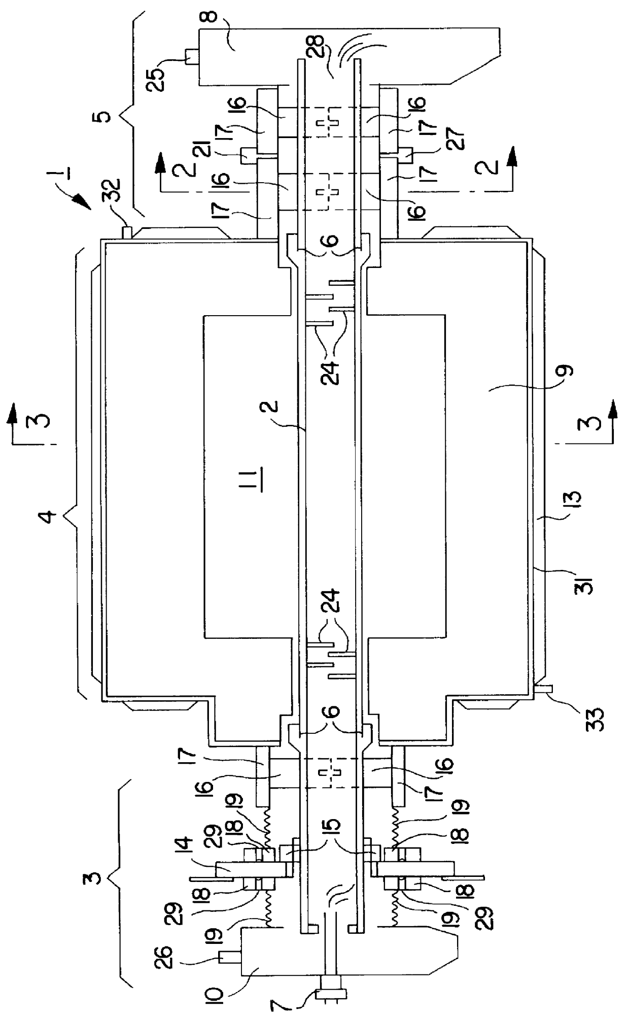
In FIG. 1 a side sectional view of a graphite rotary tube furnace 1 of the present invention includes a graphite tube 2 comprising an entrance zone 3, a heating zone 4 and a product discharge zone 5. It will be appreciated by those skilled in the art that, although the graphite rotary tube furnace of this invention is referred to and illustrated as substantially horizontal, it may, in practice, be tilted from the horizontal to aid in the movement of materials therethrough. In the embodiment depicted, the graphite tube 2 is assembled from three sections joined by means of threaded joints 6. However, in other embodiments, the graphite tube 2 may be constructed as a single unit or of any multiplicity of sections, depending on various considerations, such as the total length required and variations in the treatment of product along the length, resulting in different replacement schedules for maintenance purposes.

Material, such as particulate material, to be treated may be introduced thr...


PUM

PropertyMeasurementUnit
temperaturesaaaaaaaaaa
temperatureaaaaaaaaaa

Abstract

A rotary tube furnace suitable for operation in controlled atmospheres at temperatures in the range of 1500 DEG to 2800 DEG comprises a generally horizontal rotatable graphite tube slidably supported on water-cooled split ring graphite bearings. The graphite tube is rotated by means of a stainless steel drive plate and is contained within a flexible atmospheric sealing assembly and enclosure for the containment of a selected atmosphere around and within the tube and allows for the co-current or counter-current flow of gas during operation. Radiation baffles in the interior of the graphite tube inhibit radiant heat loss at the ends of the tube. The graphite tube may be constructed in two or more sections having threaded ends for ease of installation as well as removal or replacement for maintenance purposes. A heating section of the tube is heated by a plurality of graphite electrical heating elements contained within an insulated heating chamber.

Description

1. Field of the InventionThis invention relates to a graphite rotary tube furnace for the high temperature treatment of various materials in an inert atmosphere.2. Prior ArtThe processing of materials at very high temperatures, for example, at temperatures of from about 1500.degree. C. to temperatures as high as 3000.degree. C. or higher presents a number of problems that must be overcome in the design of the process equipment to be used. Firstly, the choice of construction materials is limited. Graphite is often the material of choice when extreme temperatures are used. Such elevated temperatures frequently require that the treatment be carried out in an inert atmosphere, for example, a non-oxidizing atmosphere to avoid undesired reactions with the material being processed. In addition, when the equipment is constructed of graphite, the material of construction itself may react with the oxygen in air at extremely high temperatures. Thus it may be necessary, or preferable, to provid...

Claims


Application Information

Patent Timeline
Patent Type & Authority Patents(United States)
IPC IPC(8): F27B7/00F27B7/08F27B7/02F27B7/06F27B7/24F27B7/22F27B7/20F27D5/00F27D9/00F27B7/26F27B7/36F27D7/06
CPCF27B7/02F27B7/06F27B7/08F27B7/224F27B7/24F27D5/0062F27D9/00
Inventor WEIDE, CARL VANDER
Owner HARPER INT CORP
Why Eureka
Try Eureka